Author Archives: author

What is the most effective mouthwash in patients infected with covid-19 to minimize possible transmission by saliva? Update.

DOI: 10.31038/JDMR.2020315

Abstract

Objectives: To study if some antiseptic agent rinse can reduce the viral load of COVID-19 in the infected patients to minimize its virulence in respiratory tract, and therefore the contagious.

Materials and Methods:To analyze of scientific articles published in the last months, about the use and effectivity of some mouthwash against COVID-19 and write an update.

Results: Rinses, as an adjunctive measure for containing the COVID-19 transmission, are important to keep in mind, but there are very few articles on COVID-19 that cover mouthwashes.

Conclusions: A concentration of 1% – 1.5% hydrogen peroxide solution or 1% – 0.2% povidone-iodine seem to be an effective mouthwash to reduce the viral load in oral cavity of COVID-19.

Clinical Relevance: Due to COVID-19 pandemic, we are suffering, and growing information about this virus, questions about which antiseptic rinse to use to decrease the viral load is essential.

Keywords

COVID-19; dentistry, chlorhexidine, povidone iodine, antimicrobial mouth rinse, antimicrobial mouthwash.

Introduction

The zoonotic virus named 2019-nCoV or COVID-19, belongs to the Coronaviridae family, it is probably outbreakstarted with Chinese horseshoe bats (Rhinolophussinicus) [1], and although pangolism was initially thought of the most likely intermediate host [2], the publication on 20th February 2020 of the genetic analysis on the BioRxiv Server has showed that the conclusion was rushed.

An epidemic of coronavirus disease started in 2019, in Wuhan (China), and during a short period of time it is causing an outbreak of pneumonia known as severe acute respiratory syndrome coronavirus 2 (SARS- CoV-2) [3, 4].

From 31th December 2019 to 18th April 2020, 2197593 cases of COVID-19 have been reported (in accordance with the applied case definitions and testing strategies in the affected countries), including 153090 deaths (191726 infected, and 20043 deaths in Spain), and it has been recognized in 207 countries and territories around the world [5, 6], and the worst is that the number of confirmed cases and deaths continues increasing until today [3].

The predominant expression of ACE2 in the lower respiratory tract is believed to have determined the natural history of SARS as a lower respiratory tract infection. All patients were initially diagnosed by RT-PCR from oro- or nasopharyngeal swab specimens [7].

Nasopharyngeal and oropharyngeal samples were collected throughout the clinical course in all infected patients, with no statistically significant differences found in either viral loads or detection rates between the two samples. The earliest swabs were taken on first day of symptoms, with symptoms often being very mild or prodromal. All swabs from all patients taken between days 1 to 5 tested positive. The average virus RNA load was 6.76×10⁵ copies per whole swab until day 5 (maximum, 7.11X10⁸ copies/swab). Swab samples taken after day 5 had an average viral load of 3.44×10⁵ copies per swab and a detection rate of 39.93%. The last positive-testing swab sample was taken on day 28 post-onset. Average viral load in sputuTypical COVID-19 signs and symptoms include fever, cough, and shortness of breath [11]; potential atypical symptoms assessed included sore throat, chills, increased confusion, rhinorrhea or nasal congestion, myalgia, dizziness, malaise, headache, nausea, vomitiing and diarrhea [12-14].m was 7.00 x 10⁶ copies per mL (maximum, 2.35×10⁹ copies per mL) [8].

Apart from respiratory pathology, around one-fourth to one-third of the hospitalized patients in Wuhan (China), developed serious complications, such as arrhythmia and shock, and were therefore transferred to the intensive care unit (ICU) [9, 10].

Typical COVID-19 signs and symptoms include fever, cough, and shortness of breath [11]; potential atypical symptoms assessed included sore throat, chills, increased confusion, rhinorrhea or nasal congestion, myalgia, dizziness, malaise, headache, nausea, vomiting and diarrhea [12-14].

People of all ages are vulnerable to this new infectious disease, however elderly people and the existence of underlying comorbidities as cardiovascular disease, diabetes, hypertension, immunosuppression or hospitalization in the ICU [15], have a worse prognosis [10, 16]. According to the average age, in the early stage of the outbreak in Wuhan, it was 59 years [17], very similar to the data provided in Spain that, in 16th March 2020, with 710 analyzed cases, the median age was 51 years [18, 19], although the deaths were in 67.2% in elderly more 80 years old, in according Italian dates [20].

Crisis management in emergent public health event is a global problem and a difficult thesis for researchers worldwide, highlighted by World Health Organization for its vital importance to public sanitation and health, life quality and survival [21, 22].

In many infectious diseases, from bacterial or viral origin, affect the respiratory tract, and therefore with the presence of pathogens in saliva, mouthwashes have been used to reduce the viral load. The chlorhexidine (CHX) is an broad spectrum antiseptic the most used daily in a dental clinic. However, there are many others on the market but, which is the best to out down the viral load? These rinses, are effective of the new viruses as COVID-19? The aim of this article is to analyze the published bibliography to know which mouthwash is effective to reduce the viral load of COVID-19 in the infected patients to minimize its virulence and therefore transmission person-person.

Material and Methods

This is not a systematic review but an update about the use of rinses to reduce de viral load in oral cavity of COVID-19, and try to analyze which is the most effective to avoid the transmission patient-dentist or vice versa.

I looked for the publications in the last months that deal with coronavirus.

Results and Discussion

Mode of transmission is based, initially animal-to human and nowadays in sustained human-to-human spread [1]. The COVID-19 was recently identified in saliva of infected patients, and the 2019-nCoV sequence could be also detected in the self-collected saliva of most infected patients even not in nasopharyngeal aspirate, and serial saliva specimens monitoring showed declines of salivary viral load after hospitalization [23].

This coronavirus can remain suspended in aerosols and retain infectivity for long periods with the possibility for to be inhaled or transmitted via direct contact with conjunctival, nasal, or oral mucosa of oral healthcare personnel (OHCP) or cross-contamination between patients. Although, some authors explain that spread of SARS-CoV-2 through aerosols or vertical transmission (from mothers to their newborns) has to be confirmed yet [24].

There are three different pathways for COVID-19 to present in saliva: firstly, in the lower and upper respiratory tract that enters the oral cavity together with the liquid droplets frequently exchanged by these organs; secondly, in the blood can access the mouth via crevicular fluid, an oral cavity-specific exudate that contains local proteins derived from extracellular matrix and serum-derived proteins [25, 26]. Finally, another way for coronavirus happens in the oral cavity is by major- and minor-salivary gland infection, with subsequent release of particles in saliva via salivary ducts, suggesting that salivary gland cells could be an important source of COVID-19 in saliva [26, 27]. In other words, the saliva droplets to be considered as a fundamental concept is the transmission of the virus [28].

It is now believed that its interpersonal transmission occurs mainly via respiratory droplets (cough, sneeze, droplets from Plügge) and contact transmission through nasal or ocular mucosa (The Chinese Preventive Medicine Association 2020), many times generated during dental clinical procedures is expected [26]. In addition, there may be risk of fecal-oral transmission, as researchers have identified SARS-CoV-2 in the stool of patients from China and the United States Protocol of prevention.

Dental procedure generated aerosol is a potential source of cross-contamination in the dental office. In addition, to containing common oral bacteria it may include pathogenic bacteria, such as Mycobacterium tuberculosis or Legionella pneumophilia, and viruses such as HIV, hepatitis B or C virus, herpes simplex virus, influenza virus [29], and especially the virus that currently causing a global pandemic, COVID-19.

A recent study indicates that copper and paper can allow the virus to survive from 4 to over 24 hours. On the other hand, the infectious charge can be drastically reduced only after at least 48 hours for steel and 72 hours for plastic [30]. For this reason, it’s more urgent to implement strict and efficient infection control protocols for dental practices and hospitals in countries/regions that are (potentially) affected with COVID-19, strict and effective infection control protocols are urgently required [3, 29].

Researchers calculated the mean incubation to be 6.4 days (ranges 2.1 to 11.1 days). It was estimated for travellers from Wuhan with confirmed 2019-nCoV infection in the early outbreak phase, using their reported travel histories and symptom onset dates. This is essential to epidemiological case definitions, and is required to determine the appropriate duration of quarantine [31]. Protection measures are needed to fight against COVID-19.

This emerging pandemic and its severe outbreak in the Italian population have induced the Italian Government first and then the European Union and in many countries of the world, to promote drastic impact measures to “flatten the curve” of the COVID-19 infection and in turn avoid health systems (in particular, intensive care units) being overwhelmed, resulting in fewer deaths [32]. The limitation of people circulating outside their home, social distance the stoppage of almost all working activities and the request to the population to use protective masks and gloves have the main goal of minimizing the likelihood that people who are not infected come into contact with others who are already infected and probably still asymptomatic [33]

Healthcare workers and other patients in the hospital are in close contact with patients with symptomatic and asymptomatic COVID-19, and for this reason they are at higher risk of SARS-CoV-2 infection.

As always happens, healthcare professionals have been immediately involved in the national emergency, overworking, often day and night: unfortunately, small numbers of them have also become infected, and some have tragically died [28].

In the early stage of the epidemic, in an analysis of 138 hospitalized patients with COVID-19 in Wuhan, 41% were presumed to have been infected in hospital, including 29% health care workers and 12% patients hospitalized for other reasons [10].

As of 14th February 2020, a total of 1.716 health care workers in China were infected with SARS-CoV-2, consisting of 3.8% affected patients [10]. Actually, (4th April, 2020), in Spain the healthcare workers infected are about 6.500 [34].

According to these statements Spagnolo et al. [28], wrote in an article that, on 15 March 2020, the New York Times published an article entitled “The Workers Who Face the Greatest Coronavirus Risk”, where an impressive schematic figure described that dentists are the workers most exposed to the risk of being affected by COVID-19, much more than nurses and general physicians. For this reason, the dentists are often the first line of diagnosis, as they work in close contact with patients.

There should be action protocols, based on both existing guidelines and published research on the principles and practices to achieve control of dental infections, mainly addressing the characteristics of nosocomial infection, and SARS, in dental care settings, and providing recommendations on patient evaluation and infection control protocols in dentistry [3].

According to all these arguments, Meng at al. [29] published an article with relevant guidelines and research, recommending management protocols for dental practitioners and students in (potentially) affected areas, introducing the essential knowledge about COVID-19 and nosocomial infection in dental settings. For this reason, [29] established a protocol, since January 24, according to which they should only be attended at the School and Hospital of Stomatology, patients with emergent dental treatment need, under the premise of adequate protection measures. Procedures that are likely to induce coughing should be avoided (if possible) or performed cautiously [35].

Aerosol-generating procedures, such as the use of a 3-way syringe, should be minimized as much as possible. Moreover, rubber dams [36], and the use of saliva ejectors with a low volume or high volume can reduce the production of droplets and aerosols, or spatter in dental procedures of emergency  [28, 37].

If an intraoral X-ray for a correct diagnosis is needed, a panoramic radiography or cone beam (CBCT), are appropriate alternatives during the outbreak of COVID-19, because the radiographic plate can stimulate saliva secretion and coughing [36].

Efficient infection control can prevent the virus from further spreading, which makes the epidemic situation under control. The most important protective measures according toChinese experts consensus are: hand-cleaning- and medical-glove-related hand protection, mask- and goggles-related face protection, UV-related protection, eye protection, nasal and oral mucosa protection, outer ear and hair protection [37].

For this reason, and knowing that the risk of cross infection may be high among patients and oral healthcare practitioners in oral healthcare settings [3, 29], population must keep in mind the requirement of a close contact between healthcare workers and infected patients to collect nasopharyngeal or oropharyngeal samples, the possibility of a saliva self-collection can strongly reduce the risk of COVID-19 transmission [26].

Dental practice should be postponed at least 1 month for convalescing patients with SARS or infected with COVID-19. [29, 38].

Since the viral load contained in the human saliva is very high, rinses with antiseptic mouthwashes can only reduce the infectious amount but are not able to eliminate the virus in the saliva [29, 39]. Active virus replication in the upper respiratory tract puts the prospects of COVID-19 containment in perspective [7].

In this sense, a few important concepts would be useful to briefly report and discuss here or raise future research.

To reduce viral load, Samaranayake et al. [38] and the General Council of Dentists of Spain [40], based on the study of [39], recommended that the patient should must rinse during 1 minute, with a mouthwash of 1% hydrogen peroxide solution 1% o de 0.2% povidone-iodine (PVP-I) before urgent treatment [40], because for over 60 years, PVP-I formulations have been shown to limit the impact and spread of infectious diseases with potent antiviral, antibacterial and antifungal effects [41].

The solution 3% hydrogen peroxide was used by author such as Nobahar et al. [42] in the prevention of VAP, obtaining good results in reducing the bacterial load and recommend its use in routine care for the prevention of this type of pneumonia. Nevertheless, [43] that applied 1.5% hydrogen peroxide solution with a suction brush after applying 0.12% CHX oral solution using swab, in patients hospitalized in ICU, they did not get statistically significant differences comparing with the group control.

According to PVP-1, other authors, such as Meng et al. [29], advised that a preoperative concentration at 1% through gargle/mouthwash reduced the viral load in the dental aerosol and in the oral cavity and oropharynx, and consequently, it is an effective way to reduce the risk of experiencing contamination in the dental office. In addition, we must include others hygiene measures needed to reduce the severity of future SARS outbreaks [44].

Marui et al. [45], analyzed the effect of some rinse such as Cetylpyridinium chloride (CPC) 0.05% only or combinated (0.075% CPC, 0.28% zinc lactate, and 0.05% sodium fluoride), essential oils (like tea tree oil), CHX 0.12% or 0.2% and herbal mouthrinse, through the microbiological count of total number of colony-forming units (CFU). This number of CFU had a significant reduction (p<0.05) with a mean of 78.9% with CHX, 61.3% with essential oils and 61.2% with CPC. In this study, the use of a herbal mouthrinse did not result in a significant reduction in the number of CFU compared with the control product [45], however [46] obtained significant antibacterial effects against Staphylococcus aureus and Streptococcus pneumoniae, and for this reason it is an alternative to other rinses.

On the other hand, Koeman et al. [47] obtained satisfactory results when combining CHX with colistin (polypeptide antibiotic effective against resistant bacteria), but both cases used only in the prevention of ventilator-associated pneumonia (VAP). Oral CHX has also not been seen as decreasing the bacterial load of COVID-19, as the Guideline for the Diagnosis and Treatment of Novel Coronavirus Pneumonia (the 5th edition) released by the National Health Commission of the People’s Republic of China concludes that the most used rinses are those of CHX, may not be effective to kill 2019-nCoV.

Bioscience Laboratories (Bozeman, Montana 2016-2019) made a study to compare the virucidal effect of several oral rinses as iodine or CHX, obtaining efficacy to completely inactivate oral pathogens, taking 15 seconds and 30 seconds to inactivate coronavirus, where others products were ineffective [48]. Nevertheless, other studies describe to CLX as a poor and not effective antiviral agent against Coronavirus (Viruses, November 2012, 4, 3044-3068) [49], just as [50], said in their study: the virus is resistant to CHX, and therefore its use is not useful.

[3] described the first typical family case of COVID-19 treated using the Chinese traditional patent medicine Shuanghuanglian oral liquid (SHL), because of poor response to the western medicine. If SHL used extracts of three Chinese herbs, namely, honeysuckle, forsythia, and Scutellariabaicalensis, to treat cold, sore throat, and cough with fever.

The most reviewed articles about COVID-19 do not considered the use of mouth rinses as a measure to reduce viral load and therefore the risk of transmission by Pügge drops from patient to dentist, or vice versa [51, 52].

Conclusion

A concentration of 1% – 1.5% hydrogen peroxide solution or 1% – 0.2% povidone-iodine seems to be an effective mouthwash to reduce the viral load in oral cavity.

To provide legal help, guidance and protocols to the oral medical industry in dealing with public health emergencies is essential. On this way, if traditional Chinese medicine and the use of some herbal rinses have been successful, research should be conducted along these lines. Perhaps we will face other viruses like hartavirus in the near future, and we must be prepared.

Acknowledgments

Health professionals for their continuous fight to stop this pandemic and researchers who are still looking for the vaccine against COVID-19.

Thanks to Chang Chen for translate Chinese texts, and I would like to say thank you, personally, Dra. PíaLópezJornet for encouraging me to continue working and reading scientific literature, even if we are confined in Spain at these moments.

References

  1. Chan JF, Yuan S, Kok KH, To KK, Chu H et al. (2020) A familial cluster of pneumonia associated with the 2019 novel coronavirus indicating person-to-person transmission: a study of a family cluster. Lancet 395:514-523.
  2. Fan J, Liu X, Pan W, Douglas MW, Bao S (2020) Epidemiology of 2019 novel coronavirus disease in Gansu Province, China2020.Emerg Infect Dis. [crossref]
  3. Li ZY, Meng LY (2020) The prevention and control of a new coronavirus infection in department of stomatology. Zhonghua Kou Qiang Yi XueZaZhi 55:E001. [crossref]
  4. Olsen SJ, Chen MY, Liu YL, Witschi M, Ardoin A et al. (2020) European COVID-19 Work Group. Early Introduction of Severe Acute Respiratory Syndrome Coronavirus 2 into Europe.Emerg Infect Dis26. [crossref]
  5. European COVID-19 Work Group.European Centre of Desease Control. https://www.ecdc.europa.eu/en/geographical-distribution-2019-ncov-cases [accessed 4th April 2020]
  6. World Health Organization. 2020a. [Last update 4th April 2020]
  7. Corman VM, Landt O, Kaiser M, Molenkamp R, Meijer A et al. (2020) Detection of 2019 novel coronavirus (2019-nCoV) by real-time RT-PCR. Euro Surveill 25. [crossref]
  8. Wölfel R, Corman VM, Guggemos W, Seilmaier M, Zange S et al. (2020) Virological assessment of hospitalized patients with COVID-2019. Nature.[crossref]
  9. Huang C, Wang Y, Li X,  Ren L, Zhao J et al. (2020) Clinical features of patients infected with 2019 novel coronavirus in Wuhan, China. Lancet.
  10. Wang D, Hu B, Hu C, Zhu F, Liu X et al. (2020) Clinical characteristics of 138 hospitalized patients with 2019 novel coronavirus–infected pneumonia in Wuhan, China. JAMA. [crossref]
  11. CDC. Preparing for COVID-19: long-term care facilities, nursing homes. Atlanta, GA: US Department of Health and Human Services, CDC; 2020.
  12. Kimball A, Hatfield KM, Arons M, James A, Taylor J et al. (2020) Public Health – Seattle & King County; CDC COVID-19 Investigation Team Asymptomatic and Presymptomatic SARS-CoV-2 Infections in Residents of a Long-Term Care Skilled Nursing Facility – King County, Washington, March 2020. MMWR Morb Mortal Wkly Rep 69:377-381.
  13. Guan W, Ni Z, Hu Y, Liang W, Ou C et al. (2020) For the China Medical Treatment Expert Group for Covid-19*. Clinical characteristics of 2019 novel coronavirus infection in China. N Engl J Med.
  14. Ding Q, Lu P, Fan Y, Xia Y, Liu M (2020) The clinical characteristics of pneumonia patients co-infected with 2019 novel coronavirus and influenza virus in Wuhan, China. J Med Virol. [crossref]
  15. Cascella M, Rajnik M, Cuomo A, Dulebohn SC, Di Napoli R (2020) Features, Evaluation and Treatment Coronavirus (COVID-19). StatPearls [Internet]. Treasure Island (FL): StatPearls Publishing; 2020-2020 Mar 8.[crossref]
  16. Yang Y, Lu Q, Liu M, Wang Y, Zhang A et al. (2020) Epidemiological and clinical features of the 2019 novel coronavirus outbreak in China. medRxiv.
  17. Bassetti M, Vena A, Giacobbe DR (2020) The novel Chinese coronavirus (2019-nCoV) infections: Challenges for fighting the storm. Eur J Clin Invest 50:e13209. [crossref]
  18. CNE (Centro Nacional de Estadística) (2020) Informesobre la situación de COVID-19 en España. CNE. SiVies. CNM(ISCIII);
  19. Spanish Ministry of Health. https://www.mscbs.gob.es/profesionales/saludPublica/ccayes/alertasActual/nCov-China/home.htm
  20. Italian Ministry of Health. http://www.salute.gov.it/portale/news/p3_2_1_1_1.jsp?lingua=italiano&menu=notizie&p=dalministero&id=4232 [accessed 23rd March 2020]. Feb 24, JAMA 2020.
  21. Shen SM (2020) Study on issues for stomatological institutions responding to state public health emergencies. Zhonghua Kou Qiang Yi XueZaZhi55: E005. [crossref]
  22. Mahase E (2020) China coronavirus: WHO declares international emergency as death toll exceeds 200. BMJ368:m408.[crossref]
  23. To KK, Tsang OT, Chik-Yan Yip C, Chan KH, Wu TC et al. (2020) Consistent detection of 2019 novel coronavirus in saliva. Clin Infect Dis.[crossref]
  24. Guo YR, Cao QD, Hong ZS, Tan YY, Chen SD et al. (2020) The origin, transmission and clinical therapies on coronavirus disease 2019 (COVID-19) outbreak – an update on the status.Mil Med Res 7:11.[crossref]
  25. Zhu N, Zhang D, Wang W, Li X, Yang B et al. (2020) China Novel Coronavirus Investigating and Research Team. A novel coronavirus from patients with pneumonia in China. N Engl J Med382:727-733. [crossref]
  26. Sabino-Silva R, Jardim ACG, Siqueira WL (2020) Coronavirus COVID-19 impacts to dentistry and potential salivary diagnosis. Clin Oral Investig24:1619-1621[crossref]
  27. Liu L, Wei Q, Alvarez X, Wang H, Du Y et al. (2011) Epithelial cells lining salivary gland ducts are early target cells of severe acute respiratory syndrome coronavirus infection in the upper respiratory tracts of rhesus macaques. J Virol85:4025-4030. [crossref]
  28. Spagnuolo G, De Vito D, Rengo S, Tatullo M (2020) COVID-19 Outbreak: An Overview on Dentistry. IntJ Environ Res Public Health 17. [crossref]
  29. Meng L, Hua F, Bian Z (2020) Coronavirus Disease 2019 (COVID-19): Emerging and Future Challenges for Dental and Oral Medicine. J Dent Res12: 22034520914246. [crossref]
  30. vanDoremalen N, Bushmaker T, Morris D, Holbrook M, Gamble A et al. (2020) Aerosol and surface stability of HCoV-19 (SARS-CoV-2) compared to SARS-CoV-1. N EnglJ Med382:1564-1567[crossref]
  31. Backer JA, Klinkenberg D, Wallinga J (2020) Incubation period of 2019 novel coronavirus (2019-nCoV) infections among travellers from Wuhan, China, 20–28 January. Euro Surveill 25.[crossref]
  32. Stevens, H. Why Outbreaks like Coronavirus Spread Exponentially, and How to “Flatten the Curve”. Available online: https://www.washingtonpost.com/graphics/2020/world/corona-simulator/?itid=hp_hp-top-table-main_virus-simulator520pm%3Ahomepage%2Fstory-ans (accessed on 4th April 2020).
  33. Li R, Pei S, Chen B, Song Y, Zhang T et al. (2020) Substantial undocumented infection facilitates the rapid dissemination of novel coronavirus (SARS-CoV2). Science. [crossref]
  34. Instituto de Salud Carlos III. https://www.isciii.es/QueHacemos/Servicios/VigilanciaSaludPublicaRENAVE/EnfermedadesTransmisibles/Docu
    ments/INFORMES/Informes%20COVID-19.
    Informe%20nº%2020.%20Situación%20de%20COVID-19%20en%20España%20a%203%20de%20abril%20de%202020.pdf. [accessed 4th April 2020]
  35. World Health Organization. 2020b. Clinical management of severe acute respiratory infection when novel coronavirus (2019-nCoV) infection is suspected: interim guidance [23thMarch 2020].
  36. Vandenberghe B, Jacobs R, Bosmans H (2020) Modern dental imaging: a review of the current technology and clinical applications in dental practice. EurRadiol 20:2637-2655. [crossref]
  37. Yan Y, Chen H, Chen L, Cheng B, Diao P et al. (2020) Consensus of Chinese experts on protection of skin and mucous membrane barrier for healthcare workers fighting against coronavirus disease 2019. DermatolTher13: e13310. [crossref]
  38. Samaranayake L, Reid J, Evans D (1989) The efficacy of rubber dam isolation in reducing atmospheric bacterial contamination. ASDC J Dent Child 56:442-444. [crossref]
  39. PengX, Xu X, Li Y, Cheng L, Zhou X et al. (2020) Transmission routes of 2019-nCoV and controls in dental practice. Int J Oral Sci 12: 9.
  40. InformetécnicodelConsejo General de Odontólogos y Estomatólogos de España (COEE). [accessed 26th March 2020]
  41. Eggers M, Koburger-Janssen T, Eickmann M, Zorn J (2018) In Vitro Bactericidal and Virucidal Efficacy of Povidone-Iodine Gargle/Mouthwash Against Respiratory and Oral Tract Pathogens. Infect Dis Ther Jun 7:249-259.[crossref]
  42. Nobahar M, Razavi MR, Malek F, Ghorbani R (2016) Effects of hydrogen peroxide mouthwash on preventing ventilator-associated pneumonia in patients admitted to the intensive care unit. Braz J Infect Dis20:444-450. [crossref]
  43. Scannapieco FA, Yu J, Raghavendran K, Vacanti A, Owens SI et al. (2009) A randomized trial of chlorhexidinegluconate on oral bacterial pathogens in mechanically ventilated patients. CritCare13: R117. [crossref]
  44. Eggers M (2019)Infectious Disease Management and Control with Povidone Iodine. Infect Dis Ther8: 581-593. [crossref]
  45. Marui VC, Souto MLS, Rovai ES, Romito GA, Chambrone L et al. (2019) Efficacy of preproceduralmouthrinses in the reduction of microorganisms in aerosol: a systematic review. J Am Dent Assoc150:1015- 1026. [crossref]
  46. Baradari AG, Khezri HD, Arabi S (2012) Comparison of antibacterial effects of oral rinses chlorhexidine and herbal mouth wash in patients admitted to intensive care unit.BratislLekListy 113:556-560. [crossref]
  47. Koeman M, van der Ven AJ, Hak E, Moore HC, Kaasjager K et al. (2006) Oral decontamination with chlorhexidine reduces the incidence of ventilator-associated pneumonia. Am J RespirCrit Care Med 173:1348-1355. [crossref]
  48. https://www.oralhealthgroup.com/features/molecular-iodine-could-this-be-a-game-changer-for-dentistry/ [accessed 26th March 2020].
  49. Geller C, Varbanov M, Duval RE (2012) Human coronaviruses: insights into environmental resistance and its influence on the development of new antiseptic strategies. Viruses 4: 3044-3068.
  50. Kampf G, Todt D, Pfaender S, Steinmann E (2020) Persistence of coronaviruses on inanimate surfaces and their inactivation with biocidal agents. J Hosp Infect 104:246-251. [crossref]
  51. Sohrabi C, AlsafiZ, O’Neill N, Khan M, Kerwan A et al. (2020) World Health Organization declares global emergency: A review of the 2019 novel coronavirus (COVID-19). Int J Surg76:71-76. [crossref]
  52. Yu F, Du L, Ojcius DM, Pan C, Jiang S (2020) Measures for diagnosing and treating infections by a novel coronavirus responsible for a pneumonia outbreak originating in Wuhan, China.Microbes Infect22:74-79. [crossref]

Genetics of Hidradenitis Suppurativa

DOI: 10.31038/JMG.2020324

Abstract

HidradenitisSuppurativa(HS), also named acne inversa, which is a common chronic inflammatory skin disorder characterized clinically by painful lumps, abscesses and scarring. Thirty-five unique mutations in patients with HS have been identified in three of the genes that encode members of the γ-secretase complex: nicastrin (NCSTN), presenilin 1 (PSEN1), and presenilin enhancer 2 (PSENEN) as well as in POGLUT1, an Endoplasmic Reticulum (ER) O-glucosyltransferase that is involved in Notch signaling. This review summarizes research updates on genetics of HS.

Keywords

Hidradenitis suppurativa, γ-secretase, nicastrin, presenilin

Introduction

Hidradenitis Suppurativa (HS), also named acne inversa, is a common chronic inflammatory skin disorder characterized clinically by painful lumps, abscesses and scarring (OMIM # 142690). The prevalence of HS in the population is 0.10%, or 98 per 100,000 persons in the United States (US) [1,2] and three times more common in female patients (73.8% women) than male patients (26.2% men), 3-fold greater in African Americans and 2-fold greater in biracial populations than in the overall population [1]. Antibiotics, anti-inflammation regiments, acne washes and medicines, and surgical procedure are the premirary current treatment options [3]. Major surgery demonstrated improvements in the HS patients’ overall work and daily activity impairment [4]. However, the disease progression often causes scars leading immobility, markedly affecting quality of life in severe patients who have poor responses to treatments [5].

The etiology of HS is associated with multi-factoralsincuding genetics and others. HS increased an independent risk of all-cause mortality [6]. Obesity, smoking, family history and environmental factors such as diet, are known to be associated with the HS disease pathogenesis. Obesity is linked to skin barrier function, sebaceous glands and sebum production, sweat gland, lymphatics, and collagen structure and function, wound healing, microcirculation and macrocirculation [7]. Obesity and smoking increase the HS incidence [8] [9]. HS patients classified as Hurley III HS were 28% more likely to be smokers and obese [10] and four times more likely to be obese compared to the general population by meta-analysis of case-control studies in Asia, Europe, and the US [11]. One-third (31%) of the HS patients who eliminated smoking or made dietary alterations including a reduction in gluten, dairy, refined sugars, tomatos, or alcohol showed improvement in HS clinical symptoms [12]. Patients with HS were at higher risk for long-term opioid use compared with controls [13].

HS lesion counts are increased with low serum zinc and vitamin D levels. Supplementation of zinc, vitamin D, vitamin B12, or exclusion of dairy or brewer’s yeast reduced lesion resolution. Bariatric surgery often causes weight loss which may lead to HS improvement but oftenresults in more severe malnutrition thatworsens or even leads to new HS onset post bariatric surgery [11]. The complement (C) system wasfound to be significantly down-regulated in the HS skin and blood transcriptomes and the HS blood proteome [81]. Porphyromonas species, which are able cleave inactive C5 into C5a, have been identified in the HS microbiome.  C5a levels in serum and tissue correlate with disease activity and degree of neutrophilic infiltrates in HS, suggesting that complement inhibition is a promising and potential therapeutic target for HS [82]. HS lesions showed 83% bacterial culture anaerobes compred to 53% of control samples, and milleri group streptococci and actinomycetes in 33% and 26% of cases, respectively [83]. Microarray analysis demonstrated that HS lesional skin samples had significantly decreased expression of enzymes involved in generating ceramide and sphingomyelin, increased expression of enzymes that catabolize ceramide to sphingosine, and increased expression of enzymes involved in converting ceramide to galactosylceramide and gangliosides, which suggests that sphingolipid metabolismi saltered in HS lesional skin comparedwith normal skin [86]. In HS patients, the serum and HS skin lension levels of chitinase-3-like protein 1 (YKL-40) were significantly elevated, suggesting that YKL-40 maybe one of the biomarkers of HS [87].

HS patients demonstrate a significantly higher heart rate in the HS groups than in the population [14]. HS often co-existed with psoriasis. Compared to patients with psoriasis alone, HS patients with psoriasis were significantly younger and had a higher prevalence of obesity and smoking [15].

Macrophages in HS infiltrates release a variety of pro-inflammatory cytokines such as interlukins and tumornecrosis factor α (TNFα), exacerbating the inflammation. Obesity and smoking contribute to macrophage dysfunction [9]. Elevated expression of TNFα has been identified in skin lesions, such as skin tunnels, of HS patients alongwith a clustering of interleukins (IL‐8, IL‐16, IL‐1α and IL‐1β) [68] [69]. Gene-sets related to Notchsignalling and Interferonpathwaysweredifferentiallyactivated in HS lesionalcompared to non-lesional skin [80].

Adalimumab is a TNFα inhibitor which has been used in both USA and Europe for treating HS patients. Adalimumab reduced flare, showed a higher efficacy on nodules-abscesses than on draining tunnels and increased the number of patients achieving a Hidradenitis Suppurativa Clinical Response [91]. By a Genome-Wide Association Study (GWAS) analysis one single Linkage Disequilibrium (LD) block in the BCL2 gene was significantly associated with adalimumab response (lead Single-Nucleotide Polymorphism [SNP] rs 59532114). Meanwhile, a correlation of the most strongly associated SNP minor allele with increased BCL2 gene and protein expression in hair follicle tissues was observed with bioinformatic analysis and functional genomics experiments [66]. HLA alleles may affect the treatment response in HS patients treated with adalimumab. Threre were three protective HLA alleles (HLA-DQB1*05, HLA-DRB1*01, and HLA-DRB1*07) less prevalent and two risk HLA alleles (HLA-DRB1*03 and HLA-DRB1*011) more abundant in HS patients developing anti-drug antibodies to adalimumab than these not [67].

Genes Linked to HS

Genetics is assciated with the pathogenesis of HS. One third of HS patients have a family history with an autosomal dominant inherentance trait [16] which pattern suggests a single gene disorder. Thirty-five unique mutations in patients with familial or sporadic HS have been found in genes encoding three of the four genes comprising the γ-secretase complex: nicastrin (NCSTN), presenilin 1 (PSEN1), presenilin enhancer 2 (PSENEN)  [17] [18] [19] [20] [21] [22] [23] [24] [25] [26] [27] [28] [29] [30] [31] [32] [33] [34] [35] and in POGLUT1, an Endoplasmic Reticulum (ER) O-glucosyltransferase involving in Notch signaling [33] with a diversity of mutation types in Caucasian, Chinese, Japanese, Indian or African ethnic origin (Table 1) [34][35]. NCSTN possesses majority (74%, 26/35) of the mutations (6 missenses, 8 nonsenses, 6 frameshifts, and 6 in splice sites resulted in frameshift or in-frame deletions). A single frameshift PSEN1-P242LfsX11 mutation was detected in PSEN1[21]. Six mutations were found in PSENEN (18%, 6/34) (3 frameshifts, 1 nonsense, 1 splicing, 1 missense). Two mutations were in POGLU1 (1 nonsense, 1 splicing).  NCSTN-R117X and Q568X were identified in more than one ethnic population and multiple families; the rest HS-linked mutations are private to each HS family or subject. NCSTN-c.1799delTG is a two-base deletion that leads to a nonsense change L600X, while 2 splicing site mutations in NCSTN, c.582+1delG p. F145fs_X54 and c.1551+1G>A p.A486_T517del result in frame-shifts while the other 4 splicing mutations cause in-frame deletions (Table 1) [34]. HS-associated mutation types in NCSTN, PSEN1, PSENEN andPOGLU1 are missense 20% (7/35), nonsense 29% (10/35), frameshift 29% (10/35) and splicing site changes 22% (8/35).

Table 1.Mutation spectrum of NCSTN, PSEN1, PSENEN and POGLUT1 in HS patients

ID

Mutation category

Nucleotide Change

Amino Acid Change

TM

Ethnic origin

Reference

NCSTN

1

Missense

c. 223G>A

p.V75I

Yes

Chinese

36

2

c.553G>A

p.D185N

Yes

Caucasian

17

3

c.632C>G

p.P211R

Yes

Chinese

18

4

c.647A>C

p.Q216P

Yes

Chinese

36

5

c.944C>T

p.A315V

Yes

Chinese

19

6

c.1229C>T

p.A410V

Yes

Chinese

20

7

Nonsense

c. 349C>T

p.R117X

No

Chinese,
Caucasian,
African

21
20
22

8

c.477C>A

p.C159X

No

Chinese

23

9

c.497C>A

p.S166X

No

Chinese

24

10

c.1258C>T

p.Q420X

No

Chinese

94

11

c. 1300C>T

p.R434X

No

Caucasian

25

12

c. 1695T>G

p.Y565X

No

Chinese

18

13

c.1702C>T

p.Q568X

No

Caucasian
Japanese

95

14

c.1799delTG

p.L600X

No

Indian

26

15

Frameshift

c.210_211delAG

p.T70fsX18

No

Chinese

27

16

c.487delC

p.Q163SfsX39

No

Chinese

21

17

c.687insCC

p.C230PfsX31

No

Indian

26

18

c.1752delG

p.E584DfsX44

No

Chinese

21

19

c.1768A>G

p.590AfsX3

No

Caucasian

25

20

c.1912_1915delCAGT

p.S638fsX1

No

Caucasian

35

21

Splice Site

c.582+1delG

p. F145fs_X54

No

Japanese

95

21

c.996+7 G>A

p.L282_G332del

Yes

Caucasian

17

23

c.1101+1 G>A

p.E333_Q367del

Yes

Caucasian

28

24

c.1101+10 A>G

p.E333_Q367del

Yes

African

17

25

c.1352+1 G>A

p.Q393fs_X9

No

Chinese

27

26

c.1551+1G>A

p.A486_T517del

No

Chinese

21

PSEN1

27

Frameshift

c.725delC

P242LfsX11

Chinese

21

PSENEN

28

Frameshift

c.66delG

p.F23LfsX46

Chinese

21 29

29

c.66_67insG

p.F23VfsX98

Caucasian

17

30

c.279delC

p.P94SfsX51

Chinese

21

31

Nonsense

c.168T>G

p.Y56-101Pdel

Caucasian

30

32

Splicing

c.167-2A>G

p.G55-101Pdel

Chinese

31

33

Missense

c.194T>G

p.L65R

Chinese

31

POGLUT1

34

Nonsense

c.814C>T

p.R272*

Caucasian

32

35

Splicing

c.430‐1G>A

p.K246_392Ldel

Caucasian

33

HS patients who carry a mutation in NCSTN, PSEN1, PSENEN or POGLUT1 display severe or typical symptoms of HS lesions [36][17] [18] [19] [20] [21] [22] [23] [24] [25] [26] [27] [28] [29] [30] [31] [32][33]s. HS patients who carrying a PSENEN or POFUT1 mutation also have co-ocurrent Dowling–DegosDisease (DDD) syndrome), an abnormally dark skin coloring condition (hyperpigmentation) [32] [37] [38] [30] [33] while mutations in NCSTN and PSEN1 occur in patients with HS only. There were 2.8 -fold patients with complex HS demenstating increase in pathogenic variants of an innate immunity regulator pyrin (also known as marenostrin, MEFV) compared to the healthy controls in the general Turkish population [39].

Structures of HS-Linked Genetic Mutations

The putative functions of the HS-linked mutations were analyzed by in silico analysis of using a variety of programs. By SWISS-MODEL, most of the HS-linked nonsense, frameshift, and splice site mutations resulted in marked 3D structural changes, and a C-terminal end frameshift mutation NCSTN-E584DfsX44 led to a striking 3D structural change while another nearby downstream frameshift mutation NCSTN-p.590AfsX3 (6 amino acids apart) caused only a minor 3D change [34]. This finding suggests that this NCSTN-E584DfsX44 mutation is likely located at a critical site for NCSTN conformation [34]. By PolyPhen-2, SNP & Go and Proven prediction, among 6 NCSTN missense mutations, NCSTN-P211R and Q216P were most deleterious; PolyPhen-2 predicts that V75I is probably damaging and D185N, A315V and A410V are predicted to have benign or neutral effects. 62% (16/26) of NCSTN mutations are nonsense or frameshift mutations that causes a truncation of the protein product. Structurally, NCSTN contains a large extra cellular domain and a single TM [40], that is located at amino acid position 670-692. 39% (10/26)  of NCSTN mutations (6 missense mutations and 4 splicing site mutations) retain the TM region, while 61% (16/26) of other NCSTN nonsense, frameshift mutations and c.582+1delG [17] and c.1352+1 G>A (experimental confirmed) [27] lose the TM domain to become cytosolic proteins that cannot enter the cell to initial signaling (Table 1). Among 4 splicing site mutations that do not affect TM regions, 3 potentially affect two key NCSTN substrate recruitment sites Gry333 and Tyr337. The p. L282_G332del occurs next to a residue of the NCSTN substrate recruitment site G333; and E333_Q367del and E333_Q367del completely abolish the 2 NCSTN substrate recruitment sites Gry333 and Tyr337 [40], which suggest that these NCSTN mutations affect important substrate recruitment structures. 50% (3/6) of the NCSTN splicing site mutations affect substrate recruitment [34].

Post Translation of HS-Linked Genetic Mutations

NCSTN mutatioNS Y565X occurs on a tyrosine phosphorylation site and R434X occurs on a glycosylation site. NCSTN-R434X disrupts the protein immediately before Asn435, one of the two NCSTN prominent glycans Asn55 and Asn435 [40]. 21% (5 of 24) of the NCSTN mutations, NCTSN-P211R, L600X, C230PfsX31, P590AfsX3 and F145fs_X54 occur at cysteine residues participating in disulfide bonds [41] [42]. Six potential NCSTN ubiquitination sites are predicted:  K78, T127, K386, K403, K591 and K597. Six residues in NCSTN undergo sumolyation: G146, S341, K386, P423, T459, and D476. NCSTN-P590AfsX3 occurs immediately before the predicted ubiquitination site K591 and abolishes two ubiquitination sites – K591 and K597. F145fs_X54 abolishes sumolyation site G146. Both NCSTN- E333_Q367del and E333_Q367del abolish sumolyation site S341. NCSTN-T70fsX18 and R117X abolish all the ubiquitination and sumolyation sites and C159X and S166X abolish four of the six ubiquitination sites and five of the six sumolyation sites [34]. The C-terminal end frameshift mutation NCSTN-E584DfsX44 resulted in a striking 3D structural change suggesting that this mutation is likely located at a critical site for NCSTN conformation [34]. Ubiquitiation and sumoylation are involved in post-translational modification. A large number of NCSTN mutations affect predicted ubiquitiation and sumoylation sites, suggesting that post-translational modification might contribute to HS pathogenesis.

HS-Linkled Mutational Effect

HS associated mutations in NCSTN are predicted to cause a loss of function as a result of frameshift and premature translation termination and a loss of  the TM domain, to affect NCSTN substrate recruitment sites, to cause a loss or creation of new ligand binging sites, and to alter post-translational modifications and disulfide bonds [41] [42], all of which support the notion that the NCSTN mutations result in significantly reduced levels of NCT and reduced γ-secretase-mediated processing of Notch and signaling in the skin [43].  Silencing of the keratinocyte NCSTN by CRISPR-Cas9 in both the keratinocyte cell line HEK001 and an embryonic kidney cell line HEK293 showed a significantly increased expression of genes related to the type I interferon response pathway [44]. NCSTNWild Type (WT) were upregulated in myeloid cells including monocytes, macrophages and non-lymphoid dendritic cells [35]. NCSTN knockdown in HaCaT cells impaired γ-secretase activity and proliferation and differentiation of keratinocytes. Expression levels of several γ-secretase substrates involved in the Notch pathway were significantly attenuated in NCSTN-silencing HaCaT cells and the lesion from a HS patient. Phosphoinositide 3-kinase (PI3K) as well as AKT and its activated form pAKT were markedly elevated in NCSTN-silencing HaCaT cells [23]. NCSTN mutations led to decreased miR-30a-3p levels, which negatively regulated RAB31 expression. Moreover, enhanced RAB31 levels accelerated degradation of activated EGFR, leading to abnormal differentiation in keratinocytes. Familial HS patients and mouse knocked out for Ncstn showed impaired EGFR signaling and epidermal differentiation [45].

However, testing four NCSTN-missense mutations, V75I, D185N, P211R, and Q216P for their effects on mediating Notch processing and signaling demonstrated a vague role of HS-linked NCSTN mutations in HS pathogenesis. The NCSTN-V75I, D185N, and P211R mutants can function in Notch signaling in vivo; in contrast mutant Q216P failed to rescue Notch processing and nuclear signaling [46]. Mouse models where components of the ¡-secretase with resultant Notch dysregulation have been knocked out have resulted in the development of dermal cysts and histological features of follicular occlusion [21][47] although these models rapidly developed multiple squamous cell carcinomas,which is not consistent with the typical progression of HS [47]. These findings suggest that although NCSTN-V75I, D185N, and P211R and some other NCSTN mutations have a significant role in the pathogenesis of the disease, this role is through a mechanism(s) other than impaired Notch signaling.

A single frameshiftPSEN1-P242LfsX11 mutation is predicted to truncate the PS1 protein after the 5th TM domain at the cytosolic region of the N terminal, which would markedly alter the 3D structure of PS1. PSENEN contains three TMs, at amino acid positions 18-38, 60-80 and 85-101. The PSENEN N-terminus is cytoplasmic, followed by two short helices that dip into the membrane [40]. All the PSENEN mutations occur within TM regions: frameshift mutations F23LfsX46 and F23VfsX98 delete all 3 TM regions, while P94SfsX51 disrupts TM region 3. Nonsense Y56-101Pdel and c.167-2A>G splicing site mutations lead to similar disruptions of TM regions 2 & 3. The missense mutation PSENEN-L65R laysin the TM 2 region and is predicted to be deleterious. POGLUT1 is located in the lumen of the endoplasmic reticulum. Both POGLUT1-R272* and C.430-1G>A, K246* lead to an early termination of protein synthesis. POGLUT1-R272* is located in the C-terminal domain and results in a truncated form of POGLUT1 with partial loss of the C-terminal domain. The splicing site c.430‐1G>A mutation was identified in exon 4 of the POFUT1 gene in patients with HS and DDD syndrome, which potentially generates aberrant splicing with loss of functionality [33]. POGLUT1 is predicted to possess 17 ligand binding sites of interactions with chain A. Hydrogen bonds include A.Y117, A.S152, A.R158, A.R158, A.D196, A.V197, A.V197, A.L199, A.V214, A.A215, A.A215, A.S217, A.F218, A.R219, A.R219 and salt bridges: A.R158 and A.R219. Both POGLUT1- c.430‐1G>A (K246*) or R272* completely abolish ligand binding function and show significant alteration of global quality estimate by Qualitative Model Energy Analysis (QMEAN) values:  POGLUT1-WT:-71; POGLUT1- c.430‐1G>A (K246*): 0.90; and R272* 0.45, indicating a greater deviation in mutant forms from the POGLUT1-WT [34].

A higher and prolonged TNFα expression and differential gene expression of four cytokine or chemokines than that of PS1-WT in response to LPS stimulation was observed in overexpression of the HS-associated PSEN1 mutation PSEN1-P242LfsX11 in PMA-differentiated macrophages [34]. Of  the overexpressing PSEN1-WT and PSEN1-P242LfsX11 induced under-expressed genes [34],  LIF and CSF2 are essential for the proliferation and differentiation of hematopoietic progenitor cells into granulocytes and macrophages [48] [49], IL12 is critical for the activation and maintenance of immune responses [50], and BMP2 regulates stem cell activation in the process of hair follicle regeneration in the dermis [51]. Theincreased expression of proinflammatoryTNFα and the decreased expression of LIF, IL12B, CSF2, BMP2 and other genes associated with the overexpression of PSEN1-P242LfsX11 may promote inflammatory processes, impair the activation/maintenance of immune cells and reduce hair follicle regeneration [34]. HS patients with a PSEN1 mutation may benefit greatly from TNFα inhibiting agents such as infliximab, adalimumab, rituximab, and ustekinumab, in particular after anti-inflammatory regimens fail to control the disease process.

PSEN1 has pleiotropic nature [52]. PSEN1 is linked to early-onset familial Alzheimer’s Disease (AD) (OMIM # 104300), a neurodegenerative disorder and the most common form of dementia in the elderly [53]. A single frameshiftPSEN1-P242LfsX11 mutation was detected in familial HS patients [21]. More than 185 missense or inframe deletion mutations and promoter variants in PSEN1 have previously been found in patients with familial AD (http://www. alz.org/) and sporadic Dilated Cardiomyopathy (DCM) [54], and 685 genes have been associated with AD (www.alz.org). The familial HS patients with PSEN1-P242LfsX11 mutation did not show the symptoms of AD [21]. Significant differential expression of ErbB4, SCNB1, and Tie1 was observed in HS lesional skin, and of EphB2, EPHB4, KCNE1, LRP6, MUSK, SDC3, Sortilin1 were observed in blood specific to AD [55]. AD-associated PSEN1 mutations alters the -secretases cleavage of β-APP to increase Aβ 42/40 ratio resulting in Aβ plague formation and related AD pathology [21]. Overexpression or silencing of presenilin caused cardiac dysfunction in Drosophila [56]. Overexpression of PSEN1-P242LfsX11 in zebrafish embryos enhanced Notch signaling but did not affect γ-secretase cleavage of APP [57], which suggests that the involvement of the PSEN1 mutation in HS pathogenesis also has a mechanism that is independent of γ-secretase activity. Different from the effectiveness of administration of TNFα inhibitor Adalimumab in the treatment of HS patients, administration of the TNFα modulator etanercept in AD patients demonstrated no apparent effect on cognitive functioning, though TNFα has been implicated in the pathogenesis of AD [58] [59]. In AD patients, only one side of each TM helix in PS1 is affected, the hot spot of Leu219, Glu222, Leu226, Ser230, Met233, and Phe237 are placed on the same side of TM5 [40] while the HS-linked PSEN1-P242LfsX11 is on the other side of TM5 in PS1. This distribution or structure of AD-linked PSEN1 mutation is significantly different from HS-linked PSEN mutations which may indicate functional importance.

POGLUT1 is an Endoplasmic Reticulum (ER) O-glucosyltransferase that adds glucose moieties to serine residues in EGF-like repeats, such as NOTCH intracellular domain [60]. Mutations in POGLUT1, including W4X, R218X, R279PfsX3 and R279W, have been previously described in unrelated caucasian patients with Dowling-Degos disease (DDD) [32] [37] [38]. Mutations in POGLUT1 caused an approximately 50% weaker POGLU1 expression in patient lesional skin compared to controls, by immunohistologic staining for POGLUT1 [38]. In addition, a missense mutation in POGLUT1 was identified with patients with muscular dystrophy. Muscles from patients demonstrated decreased Notch signaling, dramatic reduction in satellite cell pool and a muscle-specific α-dystroglycanhypoglycosylation not present in patients’ fibroblasts, suggesting a Notch-dependent pathomechanism for this novel form of muscular dystrophy [60]. Mutations in PSENEN are also identified in DDD patients [30]. Evidence has suggested the association between decreased Notch activity and POFUT1 mutations [61]. The finding of POGLUT1 mutations in patients with HS-DDD syndrome indicates aberrant Notch signaling is involved in both HS and DDD pathogenesis. Notably, mutations in POGLUT1 and NCSTN are linked to dysregulation of Notch signaling which might also contribute to small vessel disease, as well as to vascular cognitive impairment [62].

Epigenetics of HS-Linked Genes

Significant epigenetic modifications were observed in HS skin lensions [63]. mRNA of all the studied genes were significantly under-expressed in lesional HS skin compared to healthy skin by RT-PCR analyses of The Expression of Translocation (TET) and Isocitrate Dehydrogenase (IDH) family genes in the lensional skins of HS patients, suggesting that epigenetic changes occur in HS tissue and that aberrant expression of the DNA hydroxymethylation regulators may play a role in the pathogenesis of HS [63]. HS was associated with a 1.69-fold increased odds of diabetes; however, the absolute risk difference was small and is probably not clinically relevant [64]. A significant overexpression of miRNA-155-5p, miRNA-223-5p, miRNA-31-5p, miRNA-21-5p, and miRNA-146a-5p was observed in lesional HS skin compared to healthy controls, suggesting that these miRNAs may be potential disease biomarkers and therapeutic targets for HS [65].

Acknowledgments

This work was supported by the National Institutes of Health [R01AG014713 and R01MH060009 to R.E.T; R03AR063271 and R15EB019704 to A.L.]; National Science Foundation [NSF1455613 to A.L] and the Cure Alzheimer’s Fund [to R.E.T].

References

  1. Garg A, Kirby JS, Lavian J, Lin G, Strunk A (2017) Sex- and Age-Adjusted Population Analysis of Prevalence Estimates for Hidradenitis Suppurativa in the United States. JAMA Dermatol 153: 760-764.[crossref]
  2. Wipperman J, Bragg DA, Litzner B (2019) Hidradenitis Suppurativa: Rapid Evidence Review. Am Fam Physician 100: 562-569.[crossref]
  3. Alikhan A, Lynch PJ, Eisen DB (2009) Hidradenitis suppurativa: a comprehensive review. J Am Acad Dermatol 60: 539-561.[crossref]
  4. Prens LM, Huizinga J, Janse IC, Horvath B (2019) Surgical outcomes and the impact of major surgery on quality of life, activity impairment and sexual health in hidradenitis suppurativa patients: a prospective single centre study. J Eur Acad Dermatol Venereol 33: 1941-1946.[crossref]
  5. Lasko LA, Post C, Kathju S (2008) Hidradenitis suppurativa: a disease of apocrine gland physiology. JAAPA 21: 23-25.[crossref]
  6. Reddy S, Strunk A, Garg A (2019) All-cause mortality among patients with hidradenitis suppurativa: A population-based cohort study in the United States. J Am Acad Dermatol 81: 937-942.[crossref]
  7. Yosipovitch G, DeVore A, Dawn A (2007) Obesity and the skin: skin physiology and skin manifestations of obesity. J Am Acad Dermatol 56: 901-916.[crossref]
  8. Acharya P, Mathur M (2020) Hidradenitis suppurativa and smoking: a systematic review and meta-analysis. J Am Acad Dermatol82:1006-1011[crossref]
  9. Shah A, Alhusayen R, Amini-Nik S (2017) The critical role of macrophages in the pathogenesis of hidradenitis suppurativa. Inflamm Res 66: 931-945.[crossref]
  10. Vankeviciute RA, Polozovaite B, Trapikas J, Raudonis T, Grigaitiene J et al. (2019) A 12-Year Experience of Hidradenitis Suppurativa Management. Adv Skin Wound Care 32: 1-7.[crossref]
  11. Choi F, Lehmer L, Ekelem C, Mesinkovska NA (2020) Dietary and metabolic factors in the pathogenesis of hidradenitis suppurativa: a systematic review. Int J Dermatol 59: 143-153[crossref]
  12. Dempsey A, Butt M, Kirby JS (2019) Prevalence and Impact of Dietary Avoidance among Individuals with Hidradenitis Suppurativa. Dermatology 1: 1-7.[crossref]
  13. Reddy S, Orenstein LAV, Strunk A, Garg A (2019) Incidence of Long-term Opioid Use Among Opioid-Naive Patients With Hidradenitis Suppurativa in the United States. JAMA Dermatol.[crossref]
  14. Miller IM, Ahlehoff O, Vinding G, Rytgaard H, Mogensen UB et al. (2018) Hidradenitis Suppurativa is Associated with Higher Heart Rate but Not Atrial Fibrillation: A Comparative Cross-sectional Study of 462 Individuals with Hidradenitis Suppurativa in Denmark. Acta Dermatovenerol Croat 26: 289-296.[crossref]
  15. Kridin K, Shani M, Schonmann Y, Fisher S, Shalom G et al.(2018) Psoriasis and Hidradenitis Suppurativa: A Large-scale Population-based Study. J Am Acad Dermatol.[crossref]
  16. Ingram JR (2016) The Genetics of Hidradenitis Suppurativa. Dermatol Clin 34: 23-28.[crossref]
  17. Pink AE, Simpson MA, Desai N, Dafou D, Hills A,et al. (2012) Mutations in the gamma-secretase genes NCSTN, PSENEN, and PSEN1 underlie rare forms of hidradenitis suppurativa (acne inversa). J Invest Dermatol 132: 2459-2461.[crossref]
  18. Li CR, Jiang MJ, Shen DB, Xu HX, Wang HS et al. (2011) Two novel mutations of the nicastrin gene in Chinese patients with acne inversa. Br J Dermatol 165: 415-418.[crossref]
  19. Zhang S, Meng J, Jiang M, Zhao J (2016) Characterization of a Novel Mutation in the NCSTN Gene in a Large Chinese Family with Acne Inversa. Acta Derm Venereol 96: 408-409.[crossref]
  20. Liu M, Davis JW, Idler KB, Mostafa NM, Okun MM et al. (2016) Genetic analysis of NCSTN for potential association with hidradenitis suppurativa in familial and nonfamilial patients. Br J Dermatol175: 414-416.[crossref]
  21. Wang B, Yang W, Wen W, Sun J, Su B et al. (2010) Gamma-secretase gene mutations in familial acne inversa. Science 330: 1065.[crossref]
  22. Chen S, Mattei P, You J, Sobreira NL, Hinds GA (2015) gamma-Secretase Mutation in an African American Family With Hidradenitis Suppurativa. JAMA Dermatol151: 668-670.[crossref]
  23. Xiao X, He Y, Li C, Zhang X, Xu H et al. (2016) Nicastrin mutations in familial acne inversa impact keratinocyte proliferation and differentiation through the Notch and phosphoinositide 3-kinase/AKT signalling pathways. Br J Dermatol 174: 522-532.[crossref]
  24. Ma S, Yu Y, Yu G, Zhang F (2014) Identification of one novel mutation of the NCSTN gene in one Chinese acne inversa family. Dermatologica Sinica 32: 126-128.
  25. Miskinyte S, Nassif A, Merabtene F, Ungeheuer MN, Join-Lambert O et al. (2012) Nicastrin mutations in French families with hidradenitis suppurativa. J Invest Dermatol 132: 1728-1730.[crossref]
  26. Ratnamala U, Jhala D, Jain NK, Saiyed NM, Raveendrababu M (2016) Expanding the spectrum of gamma-secretase gene mutation-associated phenotypes: two novel mutations segregating with familial hidradenitis suppurativa (acne inversa) and acne conglobata. Exp Dermatol 25: 314-316.[crossref]
  27. Liu Y, Gao M, Lv YM, Yang X, Ren YQ et al. (2011) Confirmation by exome sequencing of the pathogenic role of NCSTN mutations in acne inversa (hidradenitis suppurativa). J Invest Dermatol 131: 1570-1572.[crossref]
  28. Pink AE, Simpson MA, Brice GW, Smith CH, Desai N et al. (2011) PSENEN and NCSTN mutations in familial hidradenitis suppurativa (Acne Inversa). J Invest Dermatol 131: 1568-1570.[crossref]
  29. Liu Y, Miao T, Ma J, Shao L, Luo S et al. (2016) PSENEN c.66delG in sporadic acne inversa. Eur J Dermatol 26: 298-299.[crossref]
  30. Pavlovsky M, Sarig O, Eskin-Schwartz M, Malchin N, Bochner R et al. (2018)A phenotype combining hidradenitis suppurativa with Dowling-Degos disease caused by a founder mutation in PSENEN. Br J Dermatol 178: 502-508.[crossref]
  31. Zhou C, Wen GD, Soe LM, Xu HJ, Du J et al. (2016) Novel Mutations in PSENEN Gene in Two Chinese Acne Inversa Families Manifested as Familial Multiple Comedones and Dowling-Degos Disease. Chin Med J (Engl) 129: 2834-2839.[crossref]
  32. Duchatelet S, Clerc H, Machet L, Gaboriaud P, Miskinyte S et al. (2018) A new nonsense mutation in the POGLUT1 gene in two sisters with Dowling-Degos disease. J Eur Acad Dermatol Venereol.[crossref]
  33. Gonzalez-Villanueva I, Gutierrez M, Hispan P, Betlloch I, Pascual JC (2018) Novel POFUT1 mutation associated with hidradenitis suppurativa-Dowling-Degos disease firm up a role for Notch signalling in the pathogenesis of this disorder. Br J Dermatol178: 984-986.[crossref]
  34. Li A, Peng Y, Taiclet LM, Tanzi RE (2019) Analysis of hidradenitis suppurativa-linked mutations in four genes and the effects of PSEN1-P242LfsX11 on cytokine and chemokine expression in macrophages. Hum Mol Genet 28: 1173-1182.[crossref]
  35. Allard RJV, Vossen KRS, Sigrid MA, Swagemakersn JEMM de Klein, Andrew et al. (2019) A novel nicastrin mutation in a three generation Dutch family with hidradenitis suppurativa: a search for functional significance. Journal of the European Academy of Dermatology and Venereology.
  36. Zhang C, Wang L, Chen L, Ren W, Mei A et al. (2013) Two novel mutations of the NCSTN gene in Chinese familial acne inverse. J Eur Acad Dermatol Venereol 27: 1571-1574.[crossref]
  37. Mauerer A, Betz RC, Pasternack SM, Landthaler M, Hafner C (2010) Generalized solar lentigines in a patient with a history of radon exposure. Dermatology 221: 206-210.[crossref]
  38. Basmanav FB, Oprisoreanu AM, Pasternack SM, Thiele H, Fritz G et al. (2014) Mutations in POGLUT1, encoding protein O-glucosyltransferase 1, cause autosomal-dominant Dowling-Degos disease. Am J Hum Genet 94: 135-143.[crossref]
  39. Vural S, Gundogdu M, Gokpinar Ili E, Durmaz CD, Vural A et al. (2019) Association of pyrin mutations and autoinflammation with complex phenotype hidradenitis suppurativa: a case-control study. Br J Dermatol 180: 1459-1467.[crossref]
  40. Bai Y, Dai X, Harrison AP, Chen M (2015) RNA regulatory networks in animals and plants: a long noncoding RNA perspective. Brief Funct Genomics 14: 91-101.[crossref]
  41. Sun L, Zhao L, Yang G, Yan C, Zhou R et al. (2015)Structural basis of human gamma-secretase assembly. Proc Natl Acad Sci U S A 112: 6003-6008.[crossref]
  42. Bai XC, Rajendra E, Yang G, Shi Y, Scheres SH (2015) Sampling the conformational space of the catalytic subunit of human gamma-secretase. Elife4.[crossref]
  43. Pink AE, Simpson MA, Desai N, Trembath RC, Barker JNW (2013) gamma-Secretase mutations in hidradenitis suppurativa: new insights into disease pathogenesis. J Invest Dermatol 133: 601-607.[crossref]
  44. Cao L, Morales-Heil DJ, Roberson EDO (2019) Nicastrin haploinsufficiency alters expression of type I interferon-stimulated genes: the relationship to familial hidradenitis suppurativa. Clin Exp Dermatol, 44: e118-e125.[crossref]
  45. He Y, Xu H, Li C, Zhang X, Zhou P et al. (2019) Nicastrin/miR-30a-3p/RAB31 Axis Regulates Keratinocyte Differentiation by Impairing EGFR Signaling in Familial Acne Inversa. J Invest Dermatol, 139: 124-134.[crossref]
  46. Zhang X, Sisodia SS (2015) Acne inversa caused by missense mutations in NCSTN is not fully compatible with impairments in Notch signaling. J Invest Dermatol 135: 618-20.[crossref]
  47. Frew JW, Navrazhina K (2020) No Evidence that Impaired Notch Signaling Differentiates Hidradenitis Suppurativa From Other Inflammatory Skin Diseases. Br J Dermatol182:1042-1043[crossref]
  48. Nicola NA, Babon JJ (2015) Leukemia inhibitory factor (LIF). Cytokine Growth Factor Rev26(5):533-44.[crossref]
  49. Cantrell MA, Anderson D, Cerretti DP, Price V, McKereghan K et al. (1985) Cloning, sequence, and expression of a human granulocyte/macrophage colony-stimulating factor. Proc Natl Acad Sci U S A 82: 6250-6254.[crossref]
  50. Wolf SF, Sieburth D, Sypek J (1994) Interleukin 12: a key modulator of immune function. Stem Cells 12: 154-168. [crossref]
  51. Plikus MV, Mayer JA, de la Cruz D, Baker RE, Maini PK (2008) Cyclic dermal BMP signalling regulates stem cell activation during hair regeneration. Nature 451: 340-344.[crossref]
  52. Li A, Tanzi RE (2012) Pleiotropy of presenilins. Hereditary Genetics 1: e105.
  53. Knopman DS, DeKosky ST, Cummings JL, Chui H, Corey-Bloom J et al. (2001) Practice parameter: diagnosis of dementia (an evidence-based review). Report of the Quality Standards Subcommittee of the American Academy of Neurology. Neurology56: 1143-1153.[crossref]
  54. Gianni D, Li A, Tesco G, McKay KM, Moore J et al. (2010) Protein aggregates and novel presenilin gene variants in idiopathic dilated cardiomyopathy. Circulation121: 1216-1226.[crossref]
  55. Frew JW, Navrazhina K (2019) In silico Analysis of Gamma-Secretase-Complex Mutations in Hidradenitis Suppurativa Demonstrates Disease-Specific Substrate Recognition and Cleavage Alterations. Front Med (Lausanne)6: 206.[crossref]
  56. Li A, Zhou C, Moore J, Zhang P, Tsai TH et al. (2011) Changes in the expression of the Alzheimer’s disease-associated presenilin gene in drosophila heart leads to cardiac dysfunction. Curr Alzheimer Res 8: 313-322.[crossref]
  57. Newman M, Wilson L, Verdile G, Lim A, Khan I et al. (2014) Differential, dominant activation and inhibition of Notch signalling and APP cleavage by truncations of PSEN1 in human disease. Hum Mol Genet 23: 602-617.[crossref]
  58. Tobinick E, Gross H, Weinberger A, Cohen H (2006) TNF-alpha modulation for treatment of Alzheimer’s disease: a 6-month pilot study. MedGenMed 8: 25.[crossref]
  59. Butchart J, Brook L, Hopkins V, Teeling J, Puntener U et al. (2015) Etanercept in Alzheimer disease: A randomized, placebo-controlled, double-blind, phase 2 trial. Neurology 84: 2161-2168.[crossref]
  60. Servian-Morilla E, Takeuchi H, Lee TV, Clarimon J, Mavillard F et al. (2016) A POGLUT1 mutation causes a muscular dystrophy with reduced Notch signaling and satellite cell loss. EMBO Mol Med 8: 1289-1309.[crossref]
  61. Li M, Cheng R, Liang J, Yan H, Zhang H et al. (2013) Mutations in POFUT1, encoding protein O-fucosyltransferase 1, cause generalized Dowling-Degos disease. Am J Hum Genet92: 895-903.[crossref]
  62. Montagne A, Zhao Z, Zlokovic BV (2017) Alzheimer’s disease: A matter of blood-brain barrier dysfunction? J Exp Med 214: 3151-3169.[crossref]
  63. Hessam S, Gambichler T, Skrygan M, Sand M, Ruddel I et al. (2018) Reduced ten-eleven translocation and isocitrate dehydrogenase expression in inflammatory hidradenitis suppurativa lesions. Eur J Dermatol  28: 449-456. [crossref]
  64. Phan K, Charlton O, Smith SD (2019) Hidradenitis suppurativa and diabetes mellitus: updated systematic review and adjusted meta-analysis. Clin Exp Dermatol 44: e126-e132.[crossref]
  65. Hessam S, Sand M, Skrygan M, Gambichler T, Bechara FG (2017) Expression of miRNA-155, miRNA-223, miRNA-31, miRNA-21, miRNA-125b, and miRNA-146a in the Inflammatory Pathway of Hidradenitis Suppurativa. Inflammation 40: 464-472.
  66. Liu M, Degner J, Georgantas RW, Nader A, Mostafa NM et al. (2020) A Genetic Variant in the Bcl2 Gene Associates with Adalimumab Response in Hidradenitis Suppurativa Clinical Trials and Regulates Expression of Bcl2. J Invest Dermatol140: 574-582.[crossref]
  67. Liu M, Degner J, Davis JW, Idle KB, Nader A et al. (2018) Identification of HLA-DRB1 association to adalimumab immunogenicity. PLoS One 13: e0195325. [crossref]
  68. Jorgensen AR, Thomsen SF, Karmisholt KE, RingH C (2020) Clinical, microbiological, immunological and imaging characteristics of tunnels and fistulas in hidradenitis suppurativa and Crohn’s disease. Exp Dermatol29:118-123.[crossref]
  69. Mozeika E, Pilmane M, Nurnberg BM, Jemec GB (2013) Tumour necrosis factor-alpha and matrix metalloproteinase-2 are expressed strongly in hidradenitis suppurativa. Acta Derm Venereol 93: 301-314.[crossref]
  70. Byrd AS, Carmona-Rivera C, O’Neil LJ, Carlucci PM, Cisar C et al. (2019) Neutrophil extracellular traps, B cells, and type I interferons contribute to immune dysregulation in hidradenitis suppurativa. Sci Transl Med 11.[crossref]
  71. Xie L, Huang Z, Li H, Liu X, Zheng S et al. (2019) IL-38: A New Player in Inflammatory Autoimmune Disorders. Biomolecules 9. [crossref]
  72. Bernardini N, Skroza N, Tolino E, Mambrin A, Anzalone A et al. (2020) IL-17 and its role in inflammatory, autoimmune, and oncological skin diseases: state of art. Int J Dermatol59:406-411.[crossref]
  73. Thomi R, Cazzaniga S, Seyed Jafari SM, Schlapbach C, Hunger RE (2018) Association of Hidradenitis Suppurativa With T Helper 1/T Helper 17 Phenotypes: A Semantic Map Analysis. JAMA Dermatol154: 592-595.[crossref]
  74. Scala E, Di Caprio R, Cacciapuoti S, Caiazzo G, Fusco A et al. (2019) A new T helper 17 cytokine in hidradenitis suppurativa: antimicrobial and proinflammatory role of interleukin-26. Br J Dermatol181: 1038-1045.[crossref]
  75. Thomi R, Schlapbach C, Yawalkar N, Simon D, Yerly D et al. (2018) Elevated levels of the antimicrobial peptide LL-37 in hidradenitis suppurativa are associated with a Th1/Th17 immune response. Exp Dermatol27: 172-177.[crossref]
  76. Di Caprio R, Balato A, Caiazzo G, Lembo S, Raimondo A et al. (2017) IL-36 cytokines are increased in acne and hidradenitis suppurativa. Arch Dermatol Res 309: 673-678.[crossref]
  77. Hotz C, Boniotto M, Guguin A, Surenaud M, Jean-Louis F et al. (2016) Intrinsic Defect in Keratinocyte Function Leads to Inflammation in Hidradenitis Suppurativa. J Invest Dermatol 136: 1768-1780.[crossref]
  78. Manfredini M, Giuliani AL, Ruina G, Gafa R, Bosi C et al. (2019) The P2X7 Receptor Is Overexpressed in the Lesional Skin of Subjects Affected by Hidradenitis Suppurativa: A Preliminary Study. Dermatology27: 1-8.[crossref]
  79. Coates M, Mariottoni P, Corcoran DL, Kirshner HF, Jaleel T et al. (2019) The skin transcriptome in hidradenitis suppurativa uncovers an antimicrobial and sweat gland gene signature which has distinct overlap with wounded skin. PLoS One 14: e0216249.[crossref]
  80. Shanmugam VK, Jones D, McNish S, Bendall ML, Crandall KA (2019) Transcriptome patterns in hidradenitis suppurativa: support for the role of antimicrobial peptides and interferon pathways in disease pathogenesis. Clin Exp Dermatol44:882-892.[crossref]
  81. Hoffman LK, Tomalin LE, Schultz G, Howell MD, Anandasabapathy N et al. (2018) Suarez-Farinas, M.; Lowes, M. A., Integrating the skin and blood transcriptomes and serum proteome in hidradenitis suppurativa reveals complement dysregulation and a plasma cell signature. PLoS One 13: e0203672.[crossref]
  82. Grand D, Navrazhina K, Frew JW (2019) Integrating Complement into the Molecular Pathogenesis of Hidradenitis Suppurativa. Exp Dermatol.
  83. Guet-Revillet H, Jais JP, Ungeheuer MN, Coignard-Biehler H, Duchatelet S et al. (2017) Join-Lambert, O., The Microbiological Landscape of Anaerobic Infections in Hidradenitis Suppurativa: A Prospective Metagenomic Study. Clin Infect Dis65: 282-291.[crossref]
  84. Hispan P, Murcian O, Gonzalez-Villanueva I, Frances R, Gimenez P et al. (2019) Identification of bacterial DNA in the peripheral blood of patients with active hidradenitis suppurativa. Arch Dermatol Res312:159-163.[crossref]
  85. Jones D, Banerjee A, Berger PZ, Gross A, McNish S et al. (2018) Inherent differences in keratinocyte function in hidradenitis suppurativa: Evidence for the role of IL-22 in disease pathogenesis. Immunol Invest 47: 57-70.[crossref]
  86. Dany M, Elston D (2017) Gene expression of sphingolipid metabolism pathways is altered in hidradenitis suppurativa. J Am Acad Dermatol 77: 268-273.[crossref]
  87. Salomon J, Piotrowska A, Matusiak L, Dziegiel P, Szepietowski JC (2019) Chitinase-3-like Protein 1 (YKL-40) Is Expressed in Lesional Skin in Hidradenitis Suppurativa. In Vivo 33: 141-143.
  88. Miller I, Lynggaard CD, Lophaven S, Zachariae C, Dufour DN et al. (2011) A double-blind placebo-controlled randomized trial of adalimumab in the treatment of hidradenitis suppurativa. Br J Dermatol 165: 391-398.[crossref]
  89. Kimball AB, Okun MM, Williams DA, Gottlieb AB, Papp KA et al. (2016) Two Phase 3 Trials of Adalimumab for Hidradenitis Suppurativa. N Engl J Med 375: 422-34.[crossref]
  90. van der Zee HH, Longcore M, Geng Z, Garg A (2019) Weekly adalimumab treatment decreased disease flare in hidradenitis suppurativa over 36 weeks: integrated results from the phase 3 PIONEER trials. J Eur Acad Dermatol Venereol.[crossref]
  91. Caposiena Caro RD, Cannizzaro MV, Tartaglia C, Bianchi L (2019) Clinical response rate and flares of hidradenitis suppurativa in the treatment with adalimumab. Clin Exp Dermatol.[crossref]
  92. Zouboulis CC, Hansen H, Caposiena Caro RD, Damiani G, Delorme I et al. (2020) Adalimumab Dose Intensification in Recalcitrant Hidradenitis Suppurativa/Acne Inversa. Dermatology236:25-30[crossref]
  93. Grant A, Gonzalez T, Montgomery MO, Cardenas V, Kerdel FA (2010) Infliximab therapy for patients with moderate to severe hidradenitis suppurativa: a randomized, double-blind, placebo-controlled crossover trial. J Am Acad Dermatol 62: 205-217.[crossref]
  94. Yang JQ, Wu XJ, Dou TT, Jiao T, Chen XB et al. (2015) Haploinsufficiency caused by a nonsense mutation in NCSTN underlying hidradenitis suppurativa in a Chinese family. Clin Exp Dermatol 40: 916-9.[crossref]
  95. Nomura Y, Nomura T, Suzuki S, Takeda M, Mizuno O et al. (2014) A novel NCSTN mutation alone may be insufficient for the development of familial hidradenitis suppurativa.J Dermatol Sci 74: 180-182.[crossref]

Cyber Hybrid Warfare: Asymmetric threat

DOI: 10.31038/NAMS.2020315

Abstract

Cyber hybrid warfare has been known since antiquity, it is not a new terminology nor a new practice. It can have an effect even more than a regular conventional war. The implementation of the cyber hybrid war aims to misinform, guide and manipulate citizens, disorganize the target state, create panic, overthrow governments, manipulate sensitive situations, intimidate groups, individuals and even shortened groups of the population, and finally to form an opinion according to the enemy’s beliefs. Creating online events designed to stimulate citizens to align with the strategy of governments or the strategy of the enemy government is a form of cyber hybrid warfare. The cyber hybrid warfare falls under the category of asymmetric threats as it is not possible to determine how, and the duration of the cyber invasion.The success or not of a cyber hybrid war depends on the organization, the electronic equipment, and the groups of actions they decide according to the means at their disposal to create the necessary digital entities. Finally, the cyber hybrid warfare is often used to show online military equipment aimed at downplaying its moral opponent.

Introduction

The cyber hybrid warfare also includes DeepFake, a practice mentioned in Christos Beretas previous research. The cyber hybrid war aims to disrupt and hurt the adversarial state in an organized and targeted manner, mainly regarding the organizational structure of the target state and its functioning.Digital media are used to intimidate citizens, target specific groups of people, disseminate false news between political and military leadership in order to spread hatred and resentment on both sides, to divide the people, and finally the fall of the government, followed by the anger and indignation of the people. The cyber hybrid warfare is not only and exclusively applied during a period of natural war, it is a kind of war that can be waged for years and of course in times of peace. It is difficult for citizens in a cyber hybrid war to understand the truth and lies.A well-organized cyber hybrid war is difficult for people to recognize as the facts presented are so convincing that it is impossible to recognize them as false. The ways to avoid and protect against such a war are numerous and require knowledge, experience, alertness, high morale, courage and professionalism to deal with such a cyber threat from its birth.Sovereign states around the world are using the cyber hybrid warfare to blackmail, trap, mislead, both foreign governments and citizens, achieving remote results without the use of physical violence and natural disasters. The cyber hybrid war has come to stay, and it is an emerging form of war – the pressure of the strong against the weak or better of the organized states against the disorganized. As mentioned above, a great DeepFake video is capable of stirring up enormous panic and hatred in a society. It is an asymmetric threat that is increasing day by day.

Characteristics

The cyber hybrid war is an asymmetric threat that is defined when an entity uses electronic means to disturb the peace or spread panic in the target state and launch hostilities or uproot social groups residing in it. A fake video, for example, that will be sent to targeted social groups is capable of sparking riots in the crowd with demonstrations and violence. By reading this one can easily understand the reader that the cyber hybrid war is the result of an entity preceding its onset.This entity is the digital asymmetric threat which if not handled properly then evolves into a cyber hybrid war. The cyber hybrid war is not tantamount to an isolated practice, that is, it is not a common attack on the adversarial state; rather, it consists of organized methods that are often impossible to identify, such an attack may include social media, online press, videos and hostilities from different events, etc.The difference between a cyber hybrid war and conventional warfare is that except there are no killings and conflicts, there is a constant low-level influx of information affecting the target state. That is, it does not follow the logic that an event has occurred, a number of people have risen and then the digital invasion process has ended, on the contrary, the digital presence is continuous and stable at the same level as possible.

Advanced stages of a cyber hybrid war include practices such as misinformation aimed at the financial loss of the target state, intra-country turmoil from pro-country groups that launched the cyber hybrid war to compel its citizens to withdraw. for the purpose of financial loss or even the overthrow of the government.In a cyber hybrid war, the invaders’ practical ways of attacking are not one-sided but two-sided, which means that in one field they can decrease and increase in another, for example a false bent can be seen in social media news and on the contrary the volume of fake videos is growing too.A cyber hybrid war is often won when combine electronic and physical attacks in the target state, which means that in the target state it requires the penetration of disturbing elements in order to revolt and destroy the target state’s infrastructure and economy.This includes increasing crime, which will then be used in the media and social media by the adversary state as a means of corrupting the target country with the ultimate aim of reducing its reputation, spreading fear to other countries. aimed at restricting travelers, other countries’ security reviews, further financial burden, withering and global isolation.

The success or not of a  cyber hybrid war in addition to the proper organization, hardware, and staff, requires and sufficient funding for the whole venture, funding is a key success factor, with insufficient funding the result will be the opposite, as it will unprofessionalism has emerged, and it is easy for social groups to understand that this is fake news, which is equivalent to project failure and redesign.Funding can come exclusively from the state that organizes the cyber hybrid threat, it can come from friendly countries in it, as well as from organizations that are scattered around the world, usually when a cyber hybrid war is funded by organizations around the world, the communication takes place through social media or smart phone applications that offer anonymous messaging services. At this point it should be noted that there is no formal single practice or specificity in the form of steps that need to be taken to be considered a threat as a cyber hybrid threat, so there is no legal framework defining the steps that characterize that this is a threat to the target state to take legal actions, the legal framework is incomplete and that is something that countries that are waging such wars are very aware of and they are washed.

As technology evolves, asymmetric threats increase as states with sufficient funding and equipment are able to wage such wars on a large scale, which is why the cyber hybrid wars will intensify. That is why governments and security agencies around the world are trying to organize and shield themselves against the cyber hybrid war, now knowing that its impact is greater than even conventional warfare.Preparing, organizing, and preventing such attacks are the basic prerequisites for dealing with the threat. This entails writing and implementing a cyber security policy that outlines the conditions, steps to be taken, education, definitions, and how to handle such incidents.The security policy should be updated annually and adapted to the needs and the level of risk that exists per period. It must adequately specify how government agencies must act in a period of digital asymmetric threat. Allied countries need to formulate a common cyber policy so that dealing with a digital asymmetric threat is unified. It is of no use to allies and friendly countries not to implement a common strategy against digital asymmetric threats. Friendly organized countries can easily trap the enemy and destroy the plans.

Conclusion

The cyber hybrid war is made up of several entities that, depending on the smooth functioning of all entities, are judged to be successful or unsuccessful. It is an asymmetric threat, no one can know the length or the size of the area it will take place. It is a kind of war that with the development of technology will see significant development. An important factor in success is financial support and therefore the amount of money each state is willing to spend to design and implement a credit cyber hybrid war. A well-organized and implementable cyber hybrid warfare can cause severe damage to a conventional one. It is not necessary for a cyber hybrid war to be designed exclusively by wealthy and developed countries, such a war can be created by any state that has the knowledge, money, and organization to mount an asymmetric threat. In the cyber hybrid war, the chances of convicting states for war crimes are minimized, as in the cyber hybrid war there is no clear legal framework defining the methods of intruders.Identifying a digital threat is difficult due to the complexity of its actions; identifying and neutralizing a cyber hybrid threat requires knowledge and experience of such threats. Some countries in the world have developed methods and teams to detect and manage such threats, but the measures they take to protect them are found to be incomplete and not fully effective and the reason is the rapid development of technology that new methods and techniques are constantly being discovered.Finally, as has been said above, the best defense is the organization of friendly states to provide a single aid and formulate a unified security policy that will lead to massive isolation of cyber hybrid threats. Unified repression by friendly countries against such attacks is the best organized defense against hybrid threats.

References

  1. Christos Beretas(2020)DeepFake – Another One Cyber Threat.
  2. Andreas Krieg, Jean-Marc Rickli(2019) Surrogate Warfare: The Transformation of War in the Twenty-First Century.
  3. Andrew Fevery(2018) Hybrid Warfare.

Coronavirus (COVID-19): Mode of Action that Raises Questions

DOI: 10.31038/NAMS.2020314

Opinion Article

This article is a personal opinion article and nothing more.

We are all living in the last days a state of panic wherever we are in the world. This panic is justified and owe it to the well-known Coronavirus pandemic (COVID-19) as it is officially called. The virus causes from mild to very severe symptoms, such as acute respiratory infection, that is, ARF pneumonia(AcuteRespiratoryFailure). Symptoms of the virus start from a cough, fever with tithing slowly, tiredness, and shortness of breath.

So far there is no vaccine or antibody that kills the virus. The treatments are based on antibodies created to treat the flu and pneumonia. Experimental tests of cocktail antibiotics are also used which act on a case-by-case basis in conjunction with the patient’s physical condition, concomitant illness, and age.

The way of virus actions have triggered a number of questions that I’m sure they will be of concern to you, whether you have been involved or have not found answers Important questions remain unanswered, such questions are:

• The first patient how has been infected by the virus?

• In the country where the virus first appeared, did they allow the sale of animals that had been used as experimental animals before?

• Is allowed  to sell laboratory cloned animals?

• Is it permissible to import from outside of the country laboratory created cloned animals?

• Is there evidence that animals or seafood , have the virus spread or been infected?

• Are there any announcements or publications from government sources about the study, safety and protection against such corona-viruses in the past?

• Does virus analysis show mutations based on the corona-virus structure?

Focusing on time actions of the virus, again causes questions, ranging from 2 to 14 days with an average of 5 days. Sound like the virus have hooks and try to get into the human body. By adding amino acids, a virus that could threaten humans could easily mutate.

Sound like the virus enters the human body, and after it enters, stays there and shows signs of existence after a few days, this could be concealed in such a way to protect itselfto not detected and kill it early before infect the human body, also by this way may hide the exact date of infection, so that the place of infection is not easily detected.

Analyzing the above reminds me a bit of the way HIV works, where after about a week those infected with HIV show flu or simply cold symptoms, then the symptoms subside and the carrier stays asymptomatic for years, spreading ignorant the virus.

Considering all of the above, to behave the way COVID-19 might behave, this virus may be made in the laboratory, as a biological weapon that was either accidentally escaped, or applied as a test under real conditions, or for some purpose, by whom; unknown.People who believe it is a biological weapon could think of two scenarios, the first being a real-life test, and the second being that the virus escaped from a laboratory by accident in an experimental animal or a worker.

Whatever the reality is, I hope very soon all of this will be over and everything will return to normal in our lives.

References

  1. PhD Candidate in Cyber Security (Innovative Knowledge Institute) Paris, France.
  2. Member of Alpha Beta Kappa Honor Society, Alpha of Ohio, USA.

Treatment f organophenolic and organoaromatics from textile wastewater using NiCO2O4 doped Bi2O2CO3 nanocomposite

DOI: 10.31038/NAMS.2020313

Abstract

The textile wastewaters could not be treated effectively with conventional treatment processes due to high polyphenol and aromatic compounds and colour content. In this study, by doping of NiCO2O4 to  Bi2O2CO3 the generated NiCO2O4to Bi2O2CO3nanocomposite was used for the photocatalytic oxidation of COD components (CODtotal, CODdissolved, CODinert), color, organophenols and organoaromatic compounds from a textile industry wastewaters (TW) at different operational conditions such as, at different photooxidation times (5 min, 15 min, 30 min, 60 min, 80 min and 100 min), at diferent NiCO2O4ratios (0.5wt% , 1wt%, 1.5wt%, 2wt%), at different NiCO2O4 / Bi2O2CO3nanocomposite concentrations (1, 5, 15, 30 and 45 mg/L), under 10, 30, 50 and 100 W solar irradiations, respectively. The maximum CODtotal, CODinert, total flavonols, total aromatic amines (TAAs) and color photooxidation yields were 99%, 92%, 91%, 98% and 99% respectively, under the optimized conditions, at 30 mg/L Ni/BiO nanocomposite with a Ni mass ratio of 1.5 wt% under 50 W UV (ultraviolet) light, after 60 min photooxidation time, at 25°C. The photooxidation yields of kaempferol (KPL), quercetin (QEN), patuletin (PTN), rhamnetin (RMN) and rhamnazin (RHAZ) from flavonols and 2-methoxy-5-methylaniline (MMA), 2,4-diaminoanisole(DAA); 4,40-diamino diphenyl ether (DDE), o-aminoazotoluene (OAAT), and 4-aminoazobenzol (AAB) from polyaromatic amines were > 82%.The pollutants of textile industry wastewater were effectively degraded with Ni doped BiO nanocomposite.

Keywords

Flavonols; Nickel cobaltite NiCO2O4 nanocomposite; bismuth subcarbonate (Bi2O2CO3) nanocomposite; Photooxidation; Polyaromatic amines; Ultraviolet (UV) light irradiation.

Biographical notes

Delia Teresa Sponza is a Professor at the Department of Environmental Engineering, Engineering Faculty, Dokuz Eylül University,İzmir, Turkey. She graduated her MSc and PhD degrees from Dokuz Eylül University, Turkey, in Environmental Engineering. Her research interests are environmental microbiology,environmental sciences and toxicity. She has published a number ofresearch papers at the national and international journals.

Rukiye Oztekin is a Researcher at the Department of Environmental Engineering, Engineering Faculty, Dokuz Eylül University, İzmir, Turkey. She graduated her MSc and PhD degrees from Dokuz Eylül University, Turkey, in Environmental Engineering. Her research interestsinclude environmetal sciences and toxic industrial wastewater treatment.

Introduction

Textile industry is one of those industries that consume large amounts of water in the manufacturing process [1] and, also, discharge great amounts of effluents with synthetic dyes to the environment causing public concern and legislation problems. Synthetic dyes that make up the majority (60–70%) of the dyes applied in textile processing industries [2] are considered to be serious health risk factors. Apart from the aesthetic deterioration of water bodies, many colorants and their breakdown products are toxic to aquatic life [3] and can cause harmful effects to humans [4,5]. Several physico-chemical and biological methods for dye removal from wastewater have been investigated [6-8] and seem that each technique faces the facts of technical and economical limitations [7]. The traditional physical, chemical and biologic means of wastewater treatment often have little degradation effect on this kind of pollutants. On the contrary, the technology of nanoparticulate photodegradation has been proved to be effective to them. Compared with the other conventional wastewater treatment means, this technology has such advantages as: (1) wide application, especially to the molecule structure-complexed contaminants which cannot be easily degraded by the traditional methods; (2) the nanoparticles itself have no toxicity to the health of our human livings and (3) it demonstrates a strong destructive power to the pollutants and can mineralize the pollutants into carbondipxide (CO2) and water (H2O) [9].

Bi2O2CO3 has gained much attention due to its promising photocatalytic activity for wastewater treatment [10-12]. Although Bi2O2CO3 has been widely studied in the photocatalytic degradation of wastewater, little attention has been poured to investigate the microwave catalytic performance of Bi2O2CO3 for microwave catalytic oxidation degradation of wastewater, up to now. At the same time, the magnetic NiCO2O4 has intriguing advantages, such as excellent microwave absorption performance, low cost, magnetically separable property, and high stability [13]. To the best of our knowledge, NiCO2O4-Bi2O2CO3 composite as microwave catalyst for degradation o more semiconductor photocatalysts have been found to be capable of photocatalytic degradation of organic macromolecular contaminants in wastewater [14, 15]. Therefore, photocatalytic degradation has become the most environmentally friendly, energy-saving, and efficient water pollution treatment method. In view of the fact that the traditional photocatalysts (such as TiO2) have large band gap energy and low response to visible light, their application is greatly limited. Among these miconducting photocatalysts, bismuth molybdate (Bi2MoO6) as a ternary oxide compound of Aurivillius phase becomes one of the promising materials. This is because it has a unique layered structure sandwiched between the perovskite octahedral (MoO4)2sheets and bismuth oxide layers of (Bi2O2)2+ [16-18]. Its dielectric property, ion conductivity, and catalytic performance have obvious advantages in bismuth-based semiconductors [19, 20]. Nevertheless, the light absorption property of the pure Bi2MoO6 primarily appears in the ultraviolet light region, which is only a small part of the solar spectra. Meanwhile, it presents a high recombination rate of electronhole
pairs in the process of photocatalytic reaction [21]. Therefore, researchers have improved the performance of Bi2MoO6 by means of
morphology controlling, semiconductor compounding, and doping modification [22]. Among these measures, doping has proven to be an effective method to ameliorate the surface properties of photocatalysts and enhance photocatalytic performance.

It was reported that carbon-doped Bi2MoO6 exhibited significantly enhanced and stable photocatalytic properties compared with Bi2MoO6 [23], which carbon replaced the O2anion in the lattice of Bi2MoO6, resulting in lattice expansion and grain diameter reduction, enhancement of specific surface area [24]. prepared Graphene-Bi2MoO6 (G-Bi2MoO6) hybridphotocatalysts by a simple one-step process, and an increase in photocatalytic activity was observed for G-Bi2MoO6 hybrids compared with pure Bi2MoO6 under visible light. Xing et al., (2017) reported the photocatalytic activity of 0.5% Pd–3C/BMO was robustly enhanced about 5-fold for Rhodamine B (RhB) degradation within 40 min under UV + visible light irradiation and 29-fold for O-phenylphenol (OPP) degradation within 120 min under visible light irradiation in comparison with pristine Bi2MoO6, respectively. [25] prepared a B-doped Bi2MoO6 photocatalyst with hydrothermal method by using HBO3 as a dopant source. It was found that B-doping increases the amount of Bi5+ and oxygen vacancies, so that the visible light absorption of catalyst is stronger, and the band gap energy is lower, which significantly improves the photocatalytic activity of Bi2MoO6. [26] successfully synthesized sulfur-doped copper-cobalt bimetal oxide by coprecipitation method, which significantly improved the catalytic performance and stability of the catalyst. [27] fabricated Bi2MoO6 surface co-doped with Ni2+ and Ti4+ ions through an incipient-wetness impregnation technology and calcination method, with the results suggesting Ni2+ and Ti4+ codoping increases visible-light absorption by Bi2MoO6 and promotes the separation of photogenerated charge carriers. Density functional theory calculations and systematical characterization results revealed that Biself-doping could not only promote the separation and transfer of photo generated electron-hole pairs of Bi2MoO6 but also alter the position of valence and conduction band without changing its preferential crystal orientations, morphology, visible light absorption, as well as band gap energy [28, 29] synthesized pure and various contents of Ce3+ doped Bi2MoO6 nano structures by a facile hydrothermal method. The 0.5%Ce3+ doped Bi2MoO6 exhibitsthe best photocatalytic activity of 96.6% within 20 min for RhB removal.

The photocatalytic performance of NiCO2O4-doped Bi2MoO6 nanoparticles has not been investigated extensively for the removals of aromatics and polyphenols from a textile industry. In this work, the phsicochemical properties of NiCO2O4 doped Bi2O2CO3 nanocomposite was investigated using microscope (SEM), transmission electron microscopy (TEM), Fourier transform infrared spectroscopy (FT-IR), X-ray photoelectron spectroscopy (XPS), photoluminescence spectra (PL), N2 adsorption–desorption, elemental mapping, Raman and diffused reflectances pectra (DRS) analysis. The photocatalytic oxidation of pollutant parameters [COD components (CODtotal, CODdissolved, CODinert), flavonols (kaempferol, quercetin, patuletin, rhamnetin and rhamnazin), polyaromatic amines (2-methoxy-5-methylaniline, 2,4-diaminoanisole, 4,40-diamino diphenyl ether, o-aminoazotoluene, and 4-aminoazobenzol) and color] from the TW at different operational conditions such as, at increasing photooxidation times (5 min, 15 min, 30 min, 60 min, 80 min and 100 min), at diferent Ni mass ratios (0.5wt% , 1wt%, 1.5wt%, 2wt%), at different Ni-BiO photocatalyst concentrations (1, 5, 15, 30 and 45 mg/L), at different pH ranges (4, 6, 8, 10) under 10, 30, 50 and 100 W UV light irradiations, respectively, were investigated .

Materials and methods

Raw wastewater

The characterization of raw TW was given in Table 1.

Table 1. Characterization values of TW at pH=5.7 (n=3, mean values ± SD). (SD: standard deviation; n: the repeat number of experiments in this study).

Parameters

Values

Minimum

Medium

Maximum

pH

5.00 ± 0.18

5.27 ± 0.19

6.00 ± 0.21

DO (mg/L)

1.30 ± 0.05

1.40 ± 0.05

1.50 ± 0.05

ORP (mV)

85.00 ± 2.98

106.00 ± 3.71

128.00 ± 4.48

TSS (mg/L)

285.00 ± 9.98

356.00 ± 12.46

430.00 ± 15.05

TVSS (mg/L)

192.00 ± 6.72

240.00 ± 8.40

290.00 ± 10.15

CODtotal (mg/L)

931.70 ± 32.61

1164.60 ± 40.76

1409.20 ± 49.32

CODdissolved (mg/L)

770.40 ± 26.96

962.99 ± 33.71

1165.22 ± 40.78

TOC (mg/L)

462.40 ± 16.18

578.00 ± 20.23

700.00 ± 24.50

BOD5 (mg/L)

251.50 ± 8.80

314.36 ± 11.00

380.38 ± 13.31

BOD5/CODdis

0.26 ± 0.01

0.33 ± 0.012

0.40 ± 0.014

Total N (mg/L)

24.80 ± 0.87

31.00 ± 1.09

37.51 ± 1.31

NH4-N (mg/L)

1.76 ± 0.06

2.20 ± 0.08

2.66 ± 0.09

NO3-N (mg/L)

8.00 ± 0.28

10.00 ± 0.35

12.10 ± 0.42

NO2-N (mg/L)

0.13 ± 0.05

0.16 ± 0.06

0.19 ± 0.07

Total P (mg/L)

8.80 ± 0.31

11.00 ± 0.39

13.30 ± 0.47

PO4-P (mg/L)

6.40 ± 0.22

8.00 ± 0.28

9.68 ± 0.34

SO4-2 (mg/L)

1248.00 ± 43.70

1560.00 ± 54.60

1888.00 ± 66.10

Color (1/m)

70.90 ± 2.48

88.56 ± 3.10

107.20 ± 3.75

Flavonols (mg/L)

30.9 ± 1.08

38.6 ± 1.35

46.1 ± 1.61

Flavonols

Kaempferol

4.2 ± 0.20

5.7 ± 0.2

7.2 ± 0.3

Quercetin

7.3 ± 0.26

9.2 ± 0.32

11.1 ± 0.4

Patuletin

8.3 ± 0.30

10.3 ± 0.36

12.2 ± 0.43

Rhamnetin

6.0 ± 0.21

7.2 ± 0.25

8.4 ± 0.3

Rhamnazin

5.1 ± 0.18

6.15 ± 0.22

7.2 ± 0.25

TAAs (mg benzidine/L)

891.84 ± 31.21

1038 ± 36.33

1183.8 ± 41.43

Polyaromatics

2-methoxy-5-methylaniline

128.5 ± 4.5

134.6 ±  4.71

140.6 ± 4.92

2,4-diaminoanisole

250.2 ± 8.76

275.8 ±  9.7

301.3 ± 10.6

4,40-diamino diphenyl ether

146.54 ± 5.13

156.0 ± 5.5

165.4 ± 5.8

o-aminoazotoluene

265.4 ± 9.3

293.6 ± 10.3

321.7 ± 11.3

4-aminoazobenzol

101.2 ± 3.54

178 ± 6.23

254.8 ± 8.92

Chemical structure of flavonols and poliaromatics present in the TW

The structure of flavonols in the TW was shown in Figure 1. The structure of polyaromatics in the TW was given Figure 2.
NAMS-3-1-305-g001

Figure 1. Chemical structure of flavonoids in the TW.
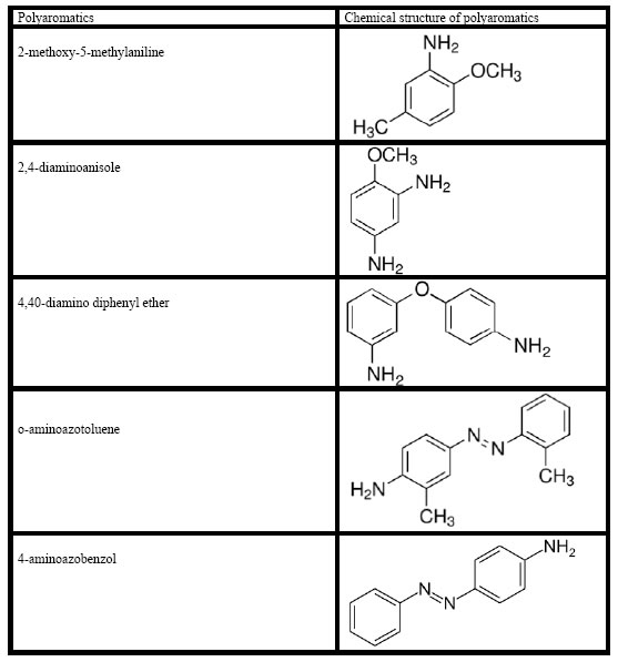
NAMS-3-1-305-g002

Figure 2. Chemical structure of polyaromatics in the TW

Preparation of photocatalysts

Ni-doped BiO nano particles were prepared by co-precipitation method using nickel nitrate hexahydrate [Ni(NO3)2.6H2O] (Analytical grade, Merck ) and Bismuthnitrate hexahydrate [Bi(NO3)2·6H2O] (Sigma, Aldrich) as the precursors of nickel and bismuth, respectively. Ni(NO3)2.6H2O and sodium carbonate anhydrous (Na2CO3) were dissolved separately in double distilled H2O to obtain 0.5 mol/Lsolutions. Nickel nitrate solution (250 mL of 0.5 mol/L) was slowly added into vigorously stirred 250 mL of 0.5 mol/L Na2CO3 solution. Nickel nitrate in the required stoichiometry was slowly added into the above solution and a white precipitate was obtained. The precipitate was filtered, repeatedly rinsed with distilled H2O and then washed twice with ethanol. The resultant solid product was dried at 100°C for 12 h and calcined at 300°C for 2 h. BiO particles were also prepared by the same procedure without the addition of nickel nitrate solution. The doping Ni mass ratios of Bismuth are expressed as wt%.

X-Ray diffraction (XRD) analysis

XRD patterns of the samples are going to carry out using a D/Max-2400Rigaku X-ray powder diffractometer operated in the reflection mode with Cu Ka (λ = 0.15418 nm) radiation through scan angle (2θ) from 20° to 80°.

Scanning electron microscopy (SEM) analysis

The morphological structures of the Ni-BiO nanocomposites before photocatalytic degradation with UV light irradiations and after photocatalytic degradation with UV by means of a SEM.

Fourier transform infrared spectroscopy (FTIR)analysis

The FTIR spectra of Ni, BiO and Ni-BiO samples were measured with FTIR spectroscopy measurements.

Photocatalytic degradation reactor

A 2 L cylinder kuvars glass reactor was used for the photodegradation experiments in the TW under different UV powers, at different operational conditions. 1000 mL TW was filled for experimental studies and the photocatalyst were added to the cylinder glass reactor. The photocatalytic reaction was operated with constant stirring during the photocatalytic degradation process. 10 mL of the reacting solution were sampled and centrifugated (at 10000 rpm) at different time intervals.

Used chemicals

Ni(NO3)2.6H2O (Analytical Grade, Merck, Germany) and Bi(NO3)3·6H2O (Analytical grade, Merck, Germany) were used as nickel and bismuth sources, respectively. Na2CO3 was purchased from Merck (Analytical grade). Helium, He(g) (GC grade, 99.98%) and nitrogen, N2(g) (GC grade, 99.98%) was purchased from Linde, (Germany). Kaempferol (99%), quercetin (99%), patuletin (99%), rhamnetin (99%), rhamnazin (99%), 2-methoxy-5-methylaniline (99%), 2,4-diaminoanisole (99%), 4,40-diamino diphenyl-ether (99%), o-aminoazotoluene (99%), 4-aminoazobenzol (99%) were purchased from Aldrich, (Germany).

Analytical methods

pH, T(°C), ORP, DO, BOD5, CODtotal, CODdissolved, total suspended solids (TSS), Total-N, NH3-N, NO3-N, NO2N, Total-P and PO4-P measurements were monitored following the Standard Methods 2310, 2320, 2550, 2580, 4500-O, 5210 B, 5220 D, 2540 D, 4500-N, 4500-NH3, 4500-NO3, 4500-NO2 and 4500-P [30]. Inert COD was measured according to glucose comparison method [31]. The samples were analyzed by high pressure liquid chromatography (HPLC) with photodiode array and mass spectrometric detection using an Agilent 1100 high performance liquid chromatography system consisting of an automatic injector, a gradient pump, a Hewlett–Packard series 1100 photodiode array detector, and an Agilent series 1100 VL on-line atmospheric pressure ionization electrospray ionization mass spectrometer to detect flavonols namely kaempferol, quercetin, patuletin, rhamnetin, rhamnazin and polyaromatics namely, 2-methoxy-5-methylaniline, 2,4-diaminoanisole, 4,40-diamino diphenyl-ether, o-aminoazotoluene, 4-aminoazobenzol, respectively. All the  metabolites were measured in the same HPLC by mass spectrometric detections. Operation of the system and data analysis were done using ChemStation software, and detection was generally done in the negative ion [M − H]– mode, which gave less complex spectra, although the positive ion mode was sometimes used to reveal fragmentation patterns—especially patterns of sugar attachment. Separation of flavonol components was made on a Vydac C18 reversed phase column (2.1 μm dia. × 250 mm long; 5-μm particle size). Columns were eluted with acetonitrile-water gradients containing 0.1% formic acid in both solvents. The quality of the raw (un-treated) and photooxidated wastewater were determined by measuring the absorbances of the supernatans at wavelengths varying between 200 nm, 250 nm, 300 nm, 350 nm and 540 nmusing an Aquamate Termoelectron Corporation UV-vis spectrophotometer.

Measurement of photonic efficiency (lr) of Ni doped BiO

The relative photonic efficiency of the catalyst is obtained by comparing the photonic efficiency of Ni-doped BiO with that of the standard photocatalyst (BiO). In order to evaluate lr, a solution of 1-Methylcyclopropene-MCP (40 mg/L) with a pH of 10 was irradiated with 100 mg of BiO and Ni-doped BiO for 60 min. From the degradation results, Ir was calculated as follows (Eq. 1).

NAMS-3-1-305-e001

Operational conditions

Under 10-30-50 and 100 W  UV light powers the photocatalytic oxidation of the pollutant parameters in the TW at different operational conditions such as at increasing Ni mass ratios in the Ni-BiOnanocomposite(0.5wt% , 1wt%, 1.5wt%, 2wt%), at increasing photooxidation times (5 min, 15 min, 30, 60 min, 80 min and 100 min), at different Ni-BiOphotocatalyst concentrations (1, 5, 15, 30 and 45 mg/L), under acidic, neutral and basic conditions, respectively.

All the experiments were carried out following the batch-wise procedure. All experiments were carried out three times and the results were given as the means of triplicate sampling with standard deviation (SD) values.

Results and analysis

XRD Analysis results

The powder XRD patterns of BiO and Ni-doped BiO with different lanthanum mass ratios are shown in Figure 3. The XRD patterns of all the Ni-doped BiO catalysts are almost similar to that of BiO, suggesting that there is no change in the crystal structure upon Ni loading. This also indicates that Ni+2 is uniformly dispersed on BiO nanoparticles in the form of small Ni2O2 cluster. However the Ni-doped samples have a wider and lower intense diffraction peaks than pure BiO. Moreover, the XRD peaks of Ni-doped BiO continuously get broader with increasing the Ni loading up to a mass ratio of 2%wt.
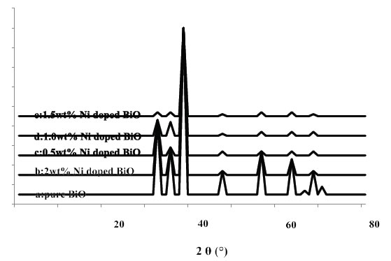
NAMS-3-1-305-g003

Figure 3. XRD patterns of BiO and Ni doped BiO (a) pure BiO, (b) 2 wt% Ni doped BiO, (c) 0.5wt% Ni doped BiO, (d) 1.0wt% Ni doped BiO, and (e) 1.5wt% Ni doped BiO.

SEM Analysis results

The morphology of nanocomposite particles is analyzed by SEM. Figure 4 shows that the nanocomposite material is partly composed of clusters containing composite nanoparticles adhering to each other with a mean size of around 20-80 nm before photooxidation process (Figure 4a) while the size increased to 24-86 nm after photooxidation (Figure 4b) with intermediates and remaining not photodegraded pollutants.
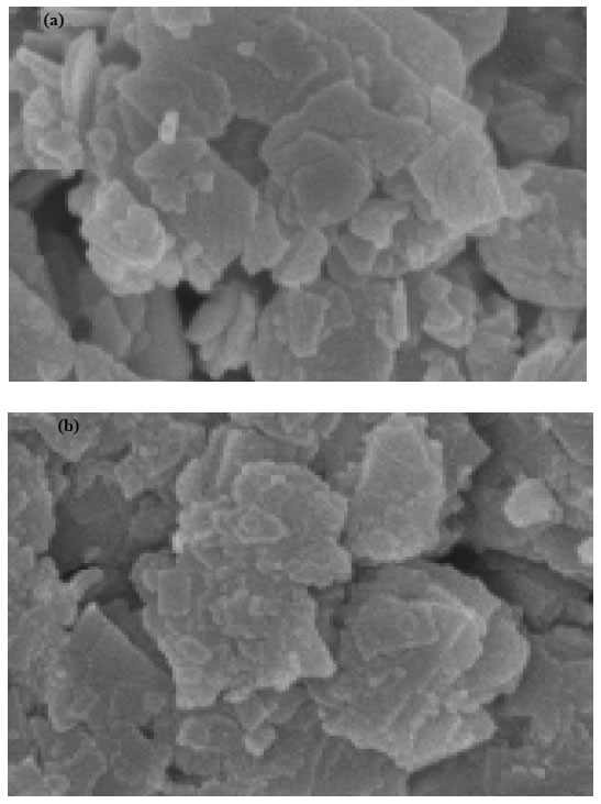
NAMS-3-1-305-g004

Figure 4. SEM micrographs of pure and nickel modified BiO, (a) pure BiO at 25°C, (b) Ni doped BiO at 25°C.

FTIR Analysis results

Figure 5 shows the FTIR spectrum of BiO and Ni-doped BiO, BiO powder synthesized under laboratory conditions. The peak between 400 and 700 cm-1 give the information of Bi–O and Ni–Bi–O on the FTIR spectra. The peak at 437–455 cm-1 give the information about stretching vibration of crystalline hexagonal zinc oxide (Bi–O stretching, vibration) and the peaks from 902 to 1020 cm-1 are attributed to the bond between lanthanum and oxygen (Ni–O). The broad peak between 3400 to 3900 cm-1 indicate the OH groups, due to the H2O which indicates the existence of atmospheric H2O adsorbed on the surface of nanocrystalline powder. An absorption band and a peak have been observed at 2350 cm-1, respectively, which arises from the absorption of atmospheric CO2 on the metal cations.
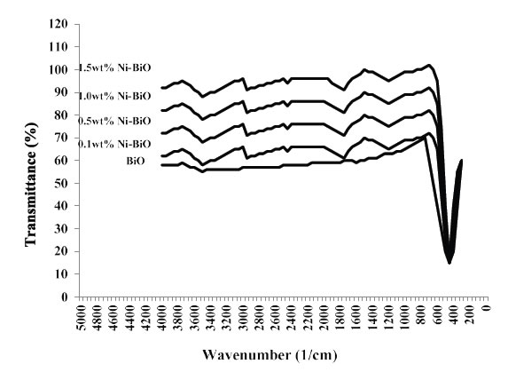
NAMS-3-1-305-g005

Figure 5. FTIR Spectra of pure BiO and Ni-doped BiO nanoparticles, with different concentration of dopant

Results and Discussions

Effect of increasing Ni-BiOnanocomposite concentrations on the removals of TW pollutants

The effects of increasing Ni-BiO nanocomposite concentrations (1 mg/L, 5 mg/L, 15 mg/L, 30 mg/L and 45 mg/L), on the photocatalytic oxidation of polutant parameters in the TW was investigated. The preliminary studies showed that the maximum removal of COD with 20 mg/L Ni-BiO nanocomposite was 89% with 70 min photooxidation time at pH=7.8 with 40 W UV power (Data not shown). Based on these yields the operational conditions for photocatalytic time were choosen as 60 min at a power of 50 W and at a pH of 8. The maximum photocatalytic oxidation removals for all pollutants in the TW were observed at 30 mg/L Ni-BiO nanocomposite concentrations, at pH=8.0, after 60 min photooxidation time and at 25°C at a power of 50 W (Figure 6). Removal efficiencies slightly decreased at 45 mg/L Ni-BiO nanocomposite concentration, because over load of surface area of Ni-BiO nanocomposites (Figure 6). This limiting the power of UV irradiation. Lower photo-removal efficiencies was measured for 1, 5, and 15 mg/L Ni-BiO concentrations due to low surface areas in the nanocomposite. On the contrarily, the surface area is high at 30 mg/L Ni-BiO nanocomposite concentrations. Therefore, the maximum photodegradation yield was observed in this nanocomposite concentration. The CODtotal, CODinert, total flavonols, total aromatic amines and color removals increased linearly as the Ni-BiO nanocomposite concentrations were increased from 1 mg/L up to 5 mg/L, to 15 mg/L, and up to 30 mg/L, respectively (Table 2 and Figure 6). Furher increase of nanocomposite concentration to 45 mg/L affect negatively the all the pollutant yields. The reason for this is the optimum amount of catalyst increases the number of active sites on the photocatalyst surface, which in turn increase the number of OH and superoxide radicals (O2 ●) to degrade pollutant parameters (COD components, flavonols, polyaromatics, color). When the concentration of the catalyst increases above the optimum value, the degradation decreases due to the interception of the light by the suspension [32]. reported that as the excess catalyst (turbidity) prevent the illumination of light, OH, a primary oxidant in the photocatalytic system decreased and the efficiency of the degradation reduced accordingly. Furthermore, the increase in catalyst concentration beyond the optimum may result in the agglomeration of catalyst particles; hence, the part of the catalyst surface becomes unavailable for photon absorption, and thereby, photocatalytic oxidation efficiency decreases [33]. Maximum CODtotal, CODinert, total flavonols, TAAs and color removal efficiencies were obtained after 60 min photooxidation process with yields of 99%, 92%, 91%, 98% and 99%, respectively, at pH=8.0, at 30 mg/L Ni-BiO nanocomposite concentration at 50 W power and at 25°C (Figure 6). Flavonols such as kaempferol, quercetin, patuletin, rhamnetin, rhamnazin removal efficiencies were 87%, 88%, 90%, 87% and 85% respectively, after 60 min photooxidation time, at pH=8.0, at 30 mg/L Ni-BiO nanocomposite concentration and at 25°C temperature (Table 2). Polyaromatic amines such as, 2-methoxy-5-methylaniline, 2,4-diaminoanisole, 4,40-diamino diphenyl ether, o-aminoazotoluene, 4-aminoazobenzol removal efficiencies after photooxidation process were 93%, 95%, 87%, 84% and 82%, respectively, after 60 min photooxidation time, at pH=8.0, at 30 mg/L Ni-BiO nanocomposite concentration at 50 W  UV power and at 25°C (Table 2).
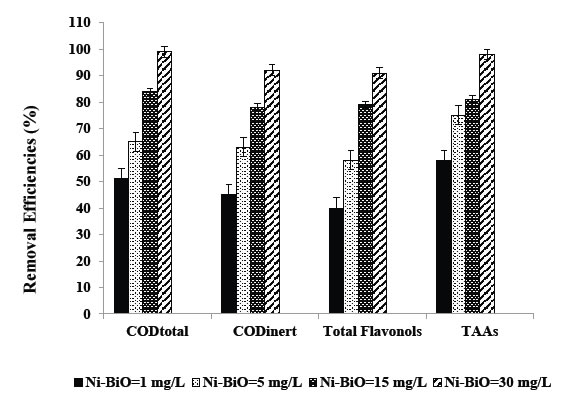
NAMS-3-1-305-g006

Figure 6. Removal efficiencies of CODtotal, CODinert, total flavonols and TAAs at Ni-BiO=1 mg/L, BiO=5 mg/L, BiO=15 mg/L and BiO=30 mg/L.

Table 2. Effect of increasing Ni-BiO nanocomposite concentrations on the TW during photooxidation process after 60 min, at 50 W UV irradiation, at pH=8.0, at 25°C.

Parameters

Removal efficiencies (%)

Ni-BiO concentrations (mg/L)

1
mg/L

5
mg/L

15
mg/L

30
mg/L

45
mg/L

CODtotal

51

65

84

99

79

CODinert

45

63

78

92

76

CODdissolved

50

64

82

98

80

Color

62

69

85

99

83

Total flavonols

40

58

79

91

72

Flavonols

Kaempferol

35

57

72

87

65

Quercetin

36

61

73

88

67

Patuletin

37

62

79

90

74

Rhamnetin

38

56

72

87

64

Rhamnazin

34

53

71

85

66

TAAs

58

75

81

98

77

Polyaromatics

2-methoxy-5-methylaniline

55

66

83

93

79

2,4-diaminoanisole

54

71

79

95

73

4,40-diamino diphenyl ether

52

58

68

87

63

o-aminoazotoluene

49

65

75

84

72

4-aminoazobenzol

47

62

76

82

70

Kaempferol metabolies such as, 3-O-[2-O,6-O-bis(α-L-rhamnosyl)-( β-D-glucosyl] quercetin, 3-O-[6-O-(α-L -rhamnosyl)-( β-D-  glucosyl]quercetin, 3-O-{2-O-[6-O-(p-hydroxy-trans-cinnamoyl)-{ )-, β-D-glucosyl]- á-L-rhamnosyl}kaempferol decreased from 5.7 mg/L to 0.86 mg/L, from 5.7 mg/L to 1.08 mg/L, from 5.7 mg/L to 1.25 mg/L, respectively, after 60 min photooxidation time, at pH=8.0, at 30 mg/L Ni-BiO nanocomposite concentration at 50 W  UV power and at 25°C (Table 3). Quercetin metabolites such as, 3-O-[6-O-( α-L -rhamnosyl)- )-(β-D-glucosyl]quercetin, 3-O-{2-O-[6-O-(p-hydroxy-trans-cinnamoyl)-( β-D -glucosyl]– á-L-rhamnosyl}quercetin reduced from 9.2 mg/L to 1.28 mg/L, from 9.2 mg/L to 2.30 mg/L, respectively, after 60 min photooxidation time, at pH=8.0, at 30 mg/L Ni-BiO nanocomposite concentration at 50 W  UV power and at 25°C (Table 3). Patuletin metabolites such as, (E)-ascladiol, (Z)-ascladiol dropped off from 10.3 mg/L to 1.55 mg/L, from 10.3 mg/L to 1.85, respectively, after 60 min photooxidation time, at pH=8.0, at 30 mg/L Ni-BiO nanocomposite concentration at 50 W  UV power and at 25°C (Table 3). Rhamnetin metabolites such as, methyl quercetin, tetrahydroxy-7-methoxyflavone decreased from 7.2 mg/L to 1.15 mg/L, from 7.2 mg/L to 1.44 mg/L, respectively, after 60 min photooxidation time, at pH=8.0, at 30 mg/L Ni-BiO nanocomposite concentration at 50 W  UV power and at 25°C (Table 3). Rhamnazin metabolites such as, Rhamnazin-3-0-β-D-glucopyranosyl-(l →5)- α-L-arabinofuranoside, Rhamnazin-3-O-β-D- glucopyranosyl-(l—»5)-[β-D-apiofuranosyl-(-1→2)]-α -L-arabinofuranoside reduced from 6.5 mg/L to 1.42 mg/L, from 6.5 mg/L to 1.66 mg/L, respectively, after 60 min photooxidation time, at pH=8.0, at 30 mg/L Ni-BiO nanocomposite concentration at 50 W  UV power and at 25°C (Table 3).

Table 3. The metabolites of flavonols in the TW.

Flavonoids

Flavonoids metabolites

Influent concentrations (mg/L)

Effluent Concentrations (mg/L)

Removal efficiencies (%)

Kaempferol

3-O-[2-O,6-O-bis(α-L-rhamnosyl)-( ß-D-glucosyl]-quercetin

5.7

0.86

85

3-O-[6-O-(α-L -rhamnosyl)-( ß-D-  glucosyl]quercetin

5.7

1.08

81

3-O-{2-O-[6-O-(p-hydroxy-trans-cinnamoyl)-{ )-, ß-D-glucosyl]- á-L-rhamnosyl}kaempferol

5.7

1.25

78

Quercetin

3-O-[6-O-(α-L -rhamnosyl)- )-( ß-D-glucosyl]quercetin

9.2

1.28

86

3-O-{2-O-[6-O-(p-hydroxy-trans-cinnamoyl)-( ß-D -glucosyl]– á-L-rhamnosyl}quercetin

9.2

2.30

75

Patuletin

(E)-ascladiol

10.3

1.55

85

(Z)-ascladiol

10.3

1.85

82

Rhamnetin

Methyl quercetin

7.2

1.15

84

Tetrahydroxy-7-methoxyflavone

7.2

1.44

80

Rhamnazin

Rhamnazin-3-0-ß-D-glucopyranosyl-(l →5)-α-L-
arabinofuranoside

6.15

1.42

77

Rhamnazin-3-O-ß-D- glucopyranosyl-(l—»5)-[ß-D-apiofuranosyl-(-1→2)]-α -L-arabinofuranoside

6.15

1.66

73

2-methoxy-5-methylaniline metabolite such as, 5-nitro-o-toluidine decreased from 134.6 mg/L to 36.34, after 60 min photooxidation time, at pH=8.0, at 30 mg/L Ni-BiO nanocomposite concentration at 50 W  UV power and at 25°C (Table 4). 2,4-diaminoanisole such as, 4-acetylamino-2-aminoanisole, 2,4-diacetylaminoanisole reduced from 275.8 mg/L to 22.06 mg/L, from 275.8 mg/L to 38.61 mg/L, respectively, after 60 min photooxidation time, at pH=8.0, at 30 mg/L Ni-BiO nanocomposite concentration at 50 W  UV power and at 25°C (Table 4). 4,40-diamino diphenyl ether metabolites such as, N,NI-diacetyl-4,4I-diaminobenzhydrol, N,NI-diacetyl-4,4 I –diaminophenylmethane dropped off from 156 mg/L to 28.08 mg/L, from 156 mg/L to 40.56 mg/L, respectively, after 60 min photooxidation time, at pH=8.0, at 30 mg/L Ni-BiO nanocomposite concentration at 50 W  UV power and at 25°C (Table 4). o-aminoazotoluene metabolites such as, hydroxy-OAT (I), 4′-hydroxy-OAAT,  2′-hydroxymethyl-3-methyl-4-aminoazobenzene, 4, 4′-bis(otolylazo)-2, 2′ -dimethylazoxybenzene decreased from 293.6 mg/L to 58.72 mg/L, from 293.6 mg/L to 79.27 mg/L, from 293.6 mg/L to 85.14 mg/L, from 293.6 mg/L to 117.44 mg/L, respectively, after 60 min photooxidation time, at pH=8.0, at 30 mg/L La-ZnO nanocomposite concentration at 50 W  UV power and at 25°C (Table 4). 4-aminoazobenzol metabolites such as phenylhydroxylamine, nitrosobenzol reduced from 178 mg/L to 39.16 mg/L, from 178 mg/L to 44.5 mg/L, respectively, after 60 min photooxidation time, at pH=8.0, at 30 mg/L Ni-BiO nanocomposite concentration at 50 W  UV power and at 25°C (Table 4).

Table 4. The metabolites of polyaromatic amines in the TW.

Polyaromatic amines

Polyaromatic amines metabolites

Influent concentrations (mg/L)

Effluent Concentrations (mg/L)

Removal efficiencies (%)

2-methoxy-5-methylaniline

5-nitro-o-toluidine

134.6

36.34

87

2,4-diaminoanisole

4-acetylamino-2-aminoanisole

275.8

22.06

92

2,4-diacetylaminoanisole

275.8

38.61

86

4,40-diamino diphenyl ether

N,NI-diacetyl-4,4I-diaminobenzhydrol

156

28.08

82

N,NI-diacetyl-4,4 I -diaminophenylmethane

156

40.56

74

o-aminoazotoluene

hydroxy-OAT (I)

293.6

58.72

80

4′ -hydroxy-OAAT

293.6

79.27

73

2′ -hydroxymethyl-3-methyl-4-aminoazobenzene

293.6

85.14

71

4, 4′-bis(otolylazo)-2, 2′ -dimethylazoxybenzene

293.6

117.44

60

4-aminoazobenzol

Phenylhydroxylamine

178

39.16

78

Nitrosobenzol

178

44.5

75

[34] researched the photocatalytic activity of pure and Ni+2-doped BiO samples for the degradation of Rhodamine B (RhB). The effect of Ni+2 doping concentration on the photocatalytic activity of RhB wasalso investigated. 9 g/L Ni+2-doped BiO with a mass ratio of 2wt% had high photocatalytic efficiency [34]. 4-nitrophenol degradation was studied in the presence of Ni doped BiO nanoparticles with a Ni mass ratio of 4% [35]. 78.26% 4-nitrophenol removal was observed the aforementioned nanocomposite after 195 min photodegradation time and at 30 W  UV light irradiation at pH=8 [35]. 68.57% Acid Yellow 29 55% Coomassie Brilliant Blue G250 and 37.27% Acid Green 25 degradations was obtained after 120 min of irradiation in the presence of 0.9% Ni-doped BiO, at 500 W UV light irradiation, under atmospheric oxygen, at 25°C, respectively [36]. The color and pollutant yields obtained in our study exhibited higher yields compared to the studies given above with low Ni-BiO nanocomposite concentrations.

Effect of increasing Ni mass ratios on 30 mg/L Ni doped BiO nanocomposite for photodegradation of TW pollutants

Were researched the effects of different La mass ratios (0.5wt%, 1wt%, 1.5wt% and 2wt% ) in 30 mg/L Ni-BiO nanocomposite concentrations on the photooxidation yields of all pollutants in the TW during photooxidation experiments. Maximum CODtotal, CODinert, total flavonols, TAAs and color removal efficiencies were 99%, 92%, 91%, 98% and 99%, respectively, after 60 min photooxidation time, at pH=8.0, at 1.5wt% Ni mass ratio and at 25°C (Table 5 and Figure 7). Removal efficiencies increased as the Ni mass ratio in the Ni doped BiO nanocomposite were increased from 0.5wt% to 1wt% and to 1.5wt%. Maximum removal efficiencies was measured at 1.5wt% Ni mass ratio in the nanocomposite. The photocatalytic degradation efficiency of BiO nanoparticles increases with an increase in the Ni loading and shows a maximum activity at 1.5 wt%. Then decreases in photooxidation yield was observed on further Ni doping (to 2 wt%). The reason of this can be explained as follows: excessive amounts of dopants can retard the photocatalysis process, because excess amount of dopants deposited on the surface of BiO increases the recombination rate of free electrons and energized holes, thus inhibiting the photodegradation process. Hence, further increase in Ni doping to 2wt% results in the decrease of photocatalytic degradation efficiency.

Table 5. Effect of increasing Ni mass ratios on the TW during photooxidation process after 60 min, at 50 W UV irradiation, 30 mg/L Ni-BiO nanocomposite concentrations, at pH=8.0, at 25°C.


Parameters

Removal efficiencies (%)

Ni mass ratios (%)

0.5wt%

1wt%

1.5wt%

2wt%

CODtotal

46

71

99

80

CODinert

40

69

92

74

CODdissolved

45

70

98

78

Color

57

76

99

81

Total flavonols

35

64

91

75

Flavonols

Kaempferol

30

63

87

68

Quercetin

31

67

88

69

Patuletin

32

68

90

75

Rhamnetin

33

62

87

68

Rhamnazin

30

60

85

67

TAAs

53

81

98

77

Polyaromatics

2-methoxy-5-methylaniline

50

72

93

69

2,4-diaminoanisole

49

77

95

75

4,40-diamino diphenyl ether

47

64

87

64

o-aminoazotoluene

44

71

84

70

4-aminoazobenzol

41

70

82

66

NAMS-3-1-305-g007

Figure 7. Removal efficiencies of CODtotal, CODinert, total flavonols and TAAs at 0.5wt%, 1wt%, 1.5wt%, and 2 wt% Ni mass ratio.

The synthesized Ni-doped BiO catalyst possesses smaller particle size distribution than pure BiO nanoparticles. Apart from their small size, as Ni+2 was doped in BiO, more surface defects are produced as reported by [37]. Consequently, the migration of the photo-induced electrons and holes toward surface defects is reasonable [37]. Thus, the separation efficiency of the electron–hole pairs of Ni-doped BiO with more oxygen defects should be more than that of the pure BiO nanoparticles. Therefore, the enhancement in the photocatalytic degradation efficiency of Ni doping BiO increases due to small particle size and higher defect concentration compared to BiO alone.

UV absorbances of Ni-doped BiO

The UV–vis absorption spectra of BiO and Ni-doped BiO are shown in Figure 8. It can be clearly seen from Figure 8. The maximum absorbance shifts is 410 nm for pure nano BiO while the maximum absorbance of Ni-doped BiO with a Ni mass ratio 0.5wt% is observed at a wavelentgh of 380 nm. The wave of absorbance of Ni-doped BiO also increases gradually with increasing the Ni loading and is much higher as compared to that of pure BiO. This could be mainly attributed to the quantum size effect as well as the strong interaction between the surface oxides of Bi and Ni. These observations strongly suggest that the Ni doping significantly affects the absorbance properties.
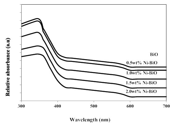
NAMS-3-1-305-g008

Figure 8. UV-vis absorption spectra of Ni doped BiO catalysts

The strong UV band gap emission (375–395 nm) results from the radiative recombination of an excited electron in the conduction band with the valence band hole. The broad visible or deep-trap state emissions (410–440 nm and 540–580 nm) are commonly defined as the recombination of the electron-hole pair from localized states with energy levels deep in the band gap, resulting in lower energy emission. These deep-trap emissions indicate the presence of defects or oxygen vacancies of BiO nanostructures [38]. Since the band gap excitation of electrons in BiO or Ni-doped BiO with 254 nm can promote electrons to the conduction band with high kinetic energy, they can reach the solid-liquid interface easily, suppressing electron–hole recombination in comparison with 365 nm. Hence, the observation of low rate at 254 nm is therefore unexpected [39]. The UV band gap emission of Ni-doped BiO nanostructures was increased between 380 and 410 nm after the photocatalytic process of pollutant parameters. The results show that 1.5 wt% Ni-doped BiO has maximum activity as compared to other photocatalysts.

Effect of increasing photooxidation time on the photooxidation yields of pollutants in the TW

Six different photooxidation times (5 min, 15 min, 30 min, 60 min, 80 min and 100 min) was examined during photocatalytic oxidation of the pollutants in the TW. To determine the optimum time for maximum removals these pollutant parameters in the TW. The maximum photocatalytic oxidation removals was observed at 60 min photooxidation time, at pH=8.0 using 30 mg/L Ni doped BiO with a La mass ratio of 1.5wt% at an UV power of 50 W (Figure 9). The removals of CODtotal, CODinert, total flavonols, total aromatic amines and color were found to increase linearly with increase in retention time from 5 min up to 80 min. A further increase in retention time to and 100 min lead to a decrease in yields of pollutant parameters. In other words the removal efficiencies of pollutant parameters (COD components, flavonols, polyaromatics, color) decreased for photooxidation time > 60 min since at long irradiation times since the surface energy of Ni doped – BiO decreases [40]. The photooxidation can form small molecules such as H2O, carbonmonoxide (CO), CO2 and benzene etc. after long irradiation; it will lead to the decrease of the polar groups and the oxygen content of pollutant surface. The dispersive component of surface energy, the density of polymer surface has great influence on dispersivity of pollutants in the TW. However, the rate of photodegradation of Ni doped-BiO blends increases with the increase of irradiation time, and is higher than that of photocrosslinking after long irradiation time, leading to the decrease of the density of the polymer surface and the dispersivity of COD, dyes and other pollutants to Ni doped–BiO [41]. The photooxidation can form small molecules such as H2O, CO, CO2 and benzene etc. after long irradiation; it will lead to the decrease of the polar groups and the oxygen content of polymer surface, therefore the dispersivity decreaeses resulting in low photooxidation yields [41]. Aromatic and phenolic metabolites which would adsorb strongly onto titania surface and block significant part of photoreactive sites.
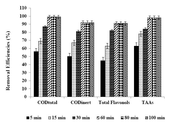
NAMS-3-1-305-g009

Figure 9. Removal efficiencies of CODtotal, CODinert total flavonols and TAAs after 5, 15, 30, 60, 80 and 100 min retention times.

The maximum CODtotal, CODinert, total flavonols, total aromatic amines and color removal efficiencies were 99%, 92%, 91%, 98% and 99%, respectively, after 60 min photooxidation time, at 1.5 wt% Ni mass ratio in 30 mg/L Ni-BiO nanocomposite concentration, at pH=8.0 and at 25°C under 50 W irradiation (Table 6). Also, flavonols such as kaempferol, quercetin, patuletin, rhamnetin, rhamnazin removal efficiencies were 87%, 88%, 90%, 87% and 85%, respectively (Table 6). The photooxidation removals of polyaromatic amines such as, 2-methoxy-5-methylaniline, 2.4-diaminoanisole, 4.40-diamino diphenyl ether, o-aminoazotoluene, 4-aminoazobenzol were 93%, 95%, 87%, 84% and 82%, respectively, after 60 min at pH=8.0 and at 25°C (Table 6). Kaempferol, quercetin, patuletin, rhamnetin, rhamnazin concentrations decreased from 5.7 to 0.741 mg/L, from 9.2 to 1.104 mg/L, from 10.3 to 1.03 mg/L, from 7.2 to 0.936 mg/L, from 6.15 to 0.923 mg/L, respectively. 2-methoxy-5-methylaniline, 2.4-diaminoanisole, 4.40-diamino diphenyl ether, o-aminoazotoluene, 4-aminoazobenzol concentrations decreased from 134.6 to 9.422 mg/L, from 275.8 to 13.79 mg/L, from 156 to 5.46 mg/L, from 293.6 to 10.28, from 178 to 6.23 mg/L, respectively.

Table 6. Effect of increasing photooxidation time on the TW during photooxidation process, at 50 W UV irradiation, at pH=8.0, 30 mg/L Ni-BiO nanocomposite concentrations, 1.5 wt% Ni mass ratio, at 25°C.


Parameters

Removal efficiencies (%)

5
min

15 min

30
min

60
min

80
min

100 min

CODtotal

56

69

87

99

99

99

CODinert

50

67

81

92

92

92

CODdissolved

55

68

85

98

98

98

Color

67

74

88

99

99

99

Total flavonols

45

63

82

91

91

91

Flavonols

Kaempferol

40

61

75

87

86

86

Quercetin

41

65

77

88

86

85

Patuletin

41

66

81

90

89

89

Rhamnetin

43

61

74

87

85

84

Rhamnazin

39

58

72

85

84

84

TAAs

63

78

84

98

98

98

Polyaromatics

2-methoxy-5-methylaniline

60

71

86

93

93

92

2,4-diaminoanisole

59

75

82

95

94

94

4,40-diamino diphenyl ether

57

62

71

87

79

78

o-aminoazotoluene

55

69

78

84

82

80

4-aminoazobenzol

51

62

75

82

81

79

The color yields obtained in this study for TW are higher than the studies given below: [42] investigated the effects of Bi0.95Ni0.05O and Bi0.90Ni0.10O on the treatment of Methylene Blue (MB) dyestuff removal under 18 UV irradiation for 1 h. 81% color yields were observed for the aforementioned Ni-Bi-O nanocomposites, respectively [42]. [43] found 80% color yields based on Reactive Black 5 after 60 min irradiation time under 90 W irradiation using Bi-Ni nanocomposite.

Effect of increasing UV powers on the yields of pollutants in the TW

In this study, four UV light powers were used (10 W, 30 W, 50 W and 100 W) to detect the optimum UV irradiation power for maximum photo-removal of the pollutant parameters in the TW using 30 mg/L Ni doped BiO nanocomposite with a Ni mass ratio of 1,5%w. The maximum photocatalytic oxidation removals was observed at 50 W  UV light irradiation, at pH=8.0, after 30 min photooxidation time and at 25°C (Table 7 and Figure 10). The CODtotal, CODinert total flavonols, total aromatic amines and color were found to increase linearly with increase in UV light irradiation from 10 W, up to 30 W, up to 50 W, respectively (Table 7 and Figure 10). Further increase of UV power up to 100 W did not affect positively the pollutant yields. Maximum CODtotal, CODinert, total flavonols, TAAs and color removal efficiencies after photooxidation process were 99%, 92%, 91%, 98% and 99%, respectively, for the aforementioned operational conditions (Figure 10). Flavonols such as kaempferol, quercetin, patuletin, rhamnetin, rhamnazin removal efficiencies were 87%, 88%, 90%, 87% and 85%, respectively, after 60 min photooxidation time, at 50 W  UV light, at pH=8.0, at 30 mg/L Ni-BiO nanocomposite concentration and at 25°C (Table 7). Polyaromatic amines such as, 2-methoxy-5-methylaniline, 2, 4-diaminoanisole, 4, 40-diamino diphenyl ether, o-aminoazotoluene, 4-aminoazobenzol removal efficiencies after photooxidation process were 93%, 95%, 87%, 84% and 82%, respectively (Table 7).

Table 7. Effect of increasing UV light irradiations on the TW during photooxidation process after 60 min, at 30 mg/L Ni-BiO photocatalyst concentration, at pH=8.0, at 25°C.

Parameters

Removal efficiencies (%)

UV light irradiation

10 W

30 W

50 W

100 W

CODtotal

49

82

99

97

CODinert

43

76

92

90

CODdissolved

48

81

98

96

Color

60

83

99

99

Total flavonols

38

76

91

90

Flavonols

Kaempferol

33

70

87

87

Quercetin

34

71

88

86

Patuletin

35

78

90

89

Rhamnetin

36

70

87

87

Rhamnazin

33

71

85

85

TAAs

56

79

98

96

Polyaromatics

2-methoxy-5-methylaniline

53

81

93

92

2,4-diaminoanisole

52

77

95

93

4,40-diamino diphenyl ether

50

66

87

86

o-aminoazotoluene

47

73

84

81

4-aminoazobenzol

45

71

82

80

NAMS-3-1-305-g010

Figure 10. Removal efficiencies of CODtotal, CODinert, total flavonols and TAAs at 10 W, 30 W, 50 W and at 100 W.

The UV power determines the extent of light absorption by the semiconductor catalyst at a given wavelength. During initiation of photocatalysis, electron–hole formation in the photochemical reaction is strongly dependent on the optimum light intensity [44]. In this study, as the UV power increase from 10 W up to 50 W might favor a high-level surface defects, which account for the increase in the defect emission relative to the UV emission as reported by [39]. Higher UV powers > 50 W decrease the defects in the surface of the nanoparticle by disturbing the active holes.

Effect of increasing pH values on the pollutant yields in the TW

The effects of increasing pH values (4.0, 6.0, 8.0 and 10.0) on the photocatalytic oxidation of polutant parameters in TW was examined by considering the solubility of BiO nanoparticles in acidic as well as in highly basic solutions. The maximum photocatalytic oxidation removals was obtained at pH=8.0, after 60 min photooxidation time with a Ni mass ratio 1.5wt% using 30 mg/L Ni-BiO nanocomposite concentration at 50 W  UV power (Table 8 and Figure 11). In acidic medium, less photocatalytic degradation of pollutant parameters (COD components, flavonols, polyaromatics, color) was observed. The extent of photocatalytic degradation of polutant parameters was found to increase with increase in initial pH to 8.0 and a decrease in maximum photocatalytic degradation was found at pH 10. The possible explanation of this is that the pH at zero point charge (zpc) of BiO is 9.0 ± 0.3 [45]. Below pH 8.0, active sites on the positively charged catalyst surface are preferentially covered by pollutant molecules. Thus, surface concentration of the polutant parameters (COD components, flavonols, polyaromatics, color) is relatively high, while those of OH and OH are low. Hence, photocatalytic degradation decreases at acidic pH. On the other hand, above pH 8.0, catalyst surface is negatively charged by means of metal-bound OH, consequently the surface concentration of the polutant parameters (COD components, flavonols, polyaromatics, color) is low, and OH is high. In addition, polutant parameters are not protonated above pH 8.0. The electrostatic repulsion between the surface charges and Ni doped BiO nanocomposite hinders the amount of polutant parameters and the adsorption, consequently surface concentration of the polutant parameters decreases, which results in the decrease of photocatalytic degradation at pH 10.0. In conclusion, pH 8.0 can provide moderate surface concentration of polutant parameters which react with the holes to form OH.

Table 8. Effect of increasing pH values on the TW during photooxidation process, at 50 W UV irradiation, after 60 min, at 25°C.


Parameters

Removal efficiencies (%)

pH values

pH=4.0

pH=6.0

pH=8.0

pH=10.0

CODtotal

53

74

99

72

CODinert

47

72

92

70

CODdissolved

52

73

98

71

Color

64

79

99

77

Total flavonols

42

68

91

66

Flavonols

Kaempferol

37

66

87

64

Quercetin

38

70

88

68

Patuletin

39

71

90

69

Rhamnetin

40

66

87

64

Rhamnazin

45

62

85

60

TAAs

60

83

98

81

Polyaromatics

2-methoxy-5-methylaniline

57

76

93

74

2,4-diaminoanisole

56

80

95

78

4,40-diamino diphenyl ether

54

67

87

65

o-aminoazotoluene

52

74

84

72

4-aminoazobenzol

50

65

82

63

NAMS-3-1-305-g011

Figure 11. Removal efficiencies of CODtotal, CODinert, total flavonols and TAAs at pH=4.0, pH=6.0, pH=8.0, pH=10.0.

Photocatalytic oxidation mechanisms of Ni doped BiOnanocomposite

The higher activity of Ni doped BiO can beattributed to successful e–h+ separation and production of ●O2 and OH. Ni-modified BiO sample manifests the highest efficiency, which may be explained by the highest number of O2 vacancies (related to the different charge and electronegativity of Ni and Bi ions) and as a result of stronger adsorption of OHions onto the BiO surface [46]. This favors the formation of OH by reaction of hole and OH. The OH and photogenerated ●O2has extremely strong non-selective oxidants lead to the degradation of the organic pollutant at the surface of Ni modified BiO [41]. The photocatalytic degradation mechanism starts with the illumination of BiO nanoparticles and production of electron–hole pairs in Eq. (2):

NAMS-3-1-305-e002

Major roles of metal ions in this study are to increase the concentration of BiO on the surface of the catalyst and to prolong the individual life-time of electrons and holes and hence, inhibit their recombination. The ability of Ni+3 to scavenge photogenerated electrons is as follows: (Eq. 3):

NAMS-3-1-305-e003

However, stabilities of Ni+3 ions may be disturbed in their reduced forms (Ni+2). This can be achieved by transferring the trapped electron to O2 [Eq. (4)]:
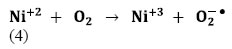
NAMS-3-1-305-e004

The produced O2● is responsible from the generation of OH, known as highly reactive electrophilic oxidants [Eqs. (5-7)]:

NAMS-3-1-305-e005-6-7

In the meantime, photogenerated holes may react with H2O molecules and produce OH (Eq. 8):

NAMS-3-1-305-e008

The color removal by photooxidation of dyes reactions were given in Eqs (9-14):
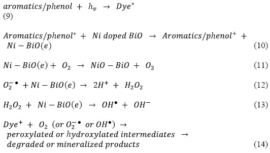
NAMS-3-1-305-e009-14

Thus, loading of metal ions such as Ni on the surface of BiO matrix can suppress the recombination of photoinduced charge carriers either with only electron capture ability or with steps forward to produce OH. For Ni–BiO, electron accepting ability, production of more OH, the highest surface roughness value and the higher dark adsorption capacity result in pronounced photoactivity. The decay profile of the products includes the subsequent attacks of OH, known as highly reactive electrophilic oxidants. The main reaction pathway (60% of OH) is the addition of the OH to the double bond of the azo group, resulting in the rapid disappearance of color; however, addition to the aromatic ring also occurs (40% of OH) [47, 48]. Further OH attacks and the increment in OH concentration in the solution increase the yield of OHadduct in the degradation progress of each product. The opening of the dye aromatic rings due to consecutive oxidation reactions leads to low-molecular weight compounds [49].

Photonic efficiency of Ni doped BiO

In order to evaluate the relative photonic efficiency (Ir), a solution of MCP (40 mg/L) adjusted to pH 10 was irradiated with 100 mg BiO (Merck) and Ni-doped BiO, separately. The relative photonic efficiencies of light of wavelengths 254 and 365 nm for BiO and Ni-doped BiO are presented in Table 9. For comparison, the relative photonic efficiency of TiO2 is also presented in Table 9. The relative photonic efficiencies of Ni-doped BiO are greater as compared to those of BiO and TiO2, revealing the effectiveness of metal-doped systems. It is also interesting to note that the relative photonic efficiency for Ni-doped BiO for light of wavelength 254 nm are much higher as compared to that for 365 nm. The results are in good agreement with degradation and mineralization studies. Comparing the high efficiency of Ni doped BiO catalysts with standard BiO and TiO2 catalyst, the photocatalytic efficiency of 1.5 wt% Ni-doped BiO is higher as compared to that of BiO and TiO2 and other Ni doped BiO nanacomposites.

Table 9. Comparison of relative photonic efficiencies in the photodegradation of pollutants in TW by BiO and Ni-doped BiO photocatalysts (*)


Parameters

Relative photonic efficiency (Ir)

256 nm

370 nm

Pure BiO

1.01 ± 0.001

0.79 ± 0.01

0.1wt% Ni–BiO

1.09 ± 0.01

0.93 ± 0.01

0.5 wt% Ni–BiO

1.28 ± 0.02

0.94 ± 0.01

1.0wt% Ni–BiO

2.59 ± 0.01

2.22 ± 0.01

1.5wt% Ni–BiO

2.98 ± 0.01

2.25 ± 0.01

2wt% Ni–BiO

1.02± 0.01

1.98 ± 0.01

Commercial BiO

1.02 ± 0.01

1.02 ± 0.01

TiO2

1.38 ± 0.01

1.03 ± 0.01

(*): pH 5; UV = 8 lamps; ë = 254 and 365 nm; 50 W UV power, 60 min photooxidation time

Reusability of Ni doped BiO

As shown in Figure 12, after the first cycle of photocatalytic oxidation within 60 min, 99% of the Ni doped BiO with a mass ratio of 1.5wt% was recovered. After three cycles, the phoooxidation ability of Ni doped BiO nanocomposite was retained at 93% of the original value. After 8th cycles the nanocomposite was reatined at 80%. One of the reasons for the slight decline in photooxidation is that the surface of the reused photocatalysts may exist with some low residual substances which did not occupy the photocatalytic sites and did not block the adsorption. The presence of Ni significantly changed the binding site of the pollutant molecules. It is possible that the oxygen atom in Ni-BiO was bound to the dopant Ni [50]. The speedily recovering of the photodegradation capacity of Ni doped BiO for pollutans photodegradation will benefit to their photocatalytic activity.
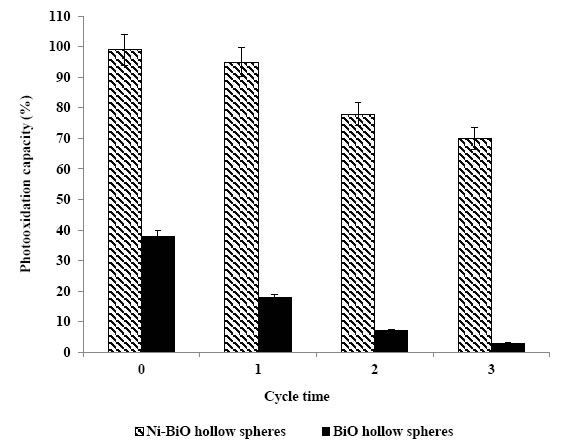
NAMS-3-1-305-g012

Figure 12. The reusability of Ni doped BiO

Conclusions

By using 30 mg/L Ni-BiO with a Ni mass ratio of 1.5w% the CODtotal, CODinert, flavonols, polyaromatics and color were photodegraded with yields as high as 82-99% within 60 min photooxidation time, at 25°C under 50 W  UV power, at pH=8.0. The addition of Ni to BiO lead to enhance the photocatalytic activity by increasing the total surface area. The flavonoids and polyaromatic amines and their metabolites in the TW were firstly determined photodegraded with high rates and photonic efficiency using 30 mg/L Ni-BiO with a Ni mass ratio of 1.5w% at pH 8.

References

  1. Lin SH, Chen ML (1997) Treatment of textile wastewater by chemical methods for reuse.Water Research31: 868-876.
  2. Van der Zee FP, Bouwman RHM, Strik DP, Lettinga G, Field JA (2001) Application of redox mediators to accelerate the transformation of reactive azo dyes in anaerobic bioreactors.Biotechnology and Bioengineering75: 691-701.[Crossref]
  3. Chung KT, Stevens SEJ (1993) Degradation of azo dyes by environmental microorganisms and helminthes.Environmental Toxicology and Chemistry 12: 2121-2132.
  4. Weisburger JH (2002) Comments on the history and importance of aromatic and heterocyclic amines in public health.Mutation Research-Fundamental and Molecular Mechanisms of Mutagenesis506: 9-20.[Crossref]
  5. Oliveira DP, Carneiro PA, Sakagami MK, Zanoni MVB, Umbuzeiro GA (2007) Chemical characterization of a dye processing plant effluent–identification of the mutagenic components.Mutation Research-Fundamental and Molecular Mechanisms of Mutagenesis626: 135-142.
  6. Robinson T, McMullan G, Marchant R, Nigam P (2001) Remediation of dyes in textile effluent: a critical review on current treatment technologies with a proposed alternative.Bioresource Technology77: 247-255.[Crossref]
  7. Van der Zee FP, Villaverde S (2005) Combined anaerobic–aerobic treatment of azo dyes—a short review of bioreactor studies.Water Research39: 1425-1440.[Crossref]
  8. Roosta M, Ghaedi M, Shokri N, Daneshfar A, Sahraei R, Asghari A (2014) ‘Experimental design based response surface methodology optimization of ultrasonic assisted adsorption of safaranin o by tin sulfide nanoparticle loaded on activated carbon. Spectrochimica Acta Part A: Molecular and Biomolecular Spectroscopy 122:  223-231.
  9. Tavakkoli H, Moayedipour T (2014) Fabrication of perovskite-type oxide La0.5Pb0.5MnO3 nanoparticles and its dye removal performance. Journal of Nanostructure in Chemistry4: 116-124.
  10. Qi X, Zhou J, Yue Z, Gui Z, Li L (2003) Auto-combustion synthesis of nanocrystalline LaFeO3.Materials Chemistry and Physics78: 25-29.
  11. Deganello F, Marcì G, Deganello G (2009) Cipate–nitrate auto-combustion synthesis of perovskite-type nanopowders: A systematic approach.Journal of the European Ceramic Society29: 439-450.
  12. Jadhav LD, Patil SP, Chavan AU, Jamale AP, Puri VR (2011)Solution combustion synthesis of Cu nanoparticles; a role of oxidant-to-fuel ratio.Micro & Nano Letters6:812-815.
  13. Shea LE, McKittrick J, Lopez OA, Sluzky E (1996) Synthesis of red-emitting, small particle size luminescent oxides using an optimized combustion process.Journal of the American Ceramic Society 79: 3257-3265.
  14. Dong SY, Feng JL, Fan MH, Pi Y, Hu L, et al. (2015) Recent developments in heterogeneous photocatalytic water treatment using visible light-responsive photocatalysts: A review.RSC Advances5: 14610-14630.
  15. Wang HL, Xu LJ, Liu CL, Lu Y, Feng Q, et al. (2019) Composite magnetic photocatalyst Bi5O7I/MnxZn1-xFe2O4:Hydrothermal-roasting preparation and enhanced photocatalytic activity.Nanomaterials 9: 118-131.
  16. Li HH, Li KW, Wang H (2009) Hydrothermal synthesis and photocatalytic properties of bismuth molybdate materials.Materials Chemistry and Physics116: 134-142.
  17. Ren J, Wang W, Shang M, Sun S, Gao E (2011) Heterostructured bismuth molybdate composite: Preparation and improved photocatalytic activity under visible-light irradiation.ACS Applied Materials & Interfaces 3: 2529-2533. [Crossref]
  18. Zhang T, Huang JF, Zhou S, Ouyang HB, Cao LY,et al. (2013) Microwave hydrothermal synthesis and optical properties of flower-like Bi2MoO6 crystallites.Ceramics International39: 7391-7394.
  19. Meng XC, Zhang ZS (2016) Bismuth-based photocatalytic semiconductors: Introduction, challenges and possible approaches.Journal of Molecular Catalysis A-Chemical423: 533-549.
  20. Jia YL, Ma Y, Tang JZ, Shi W (2018) Hierarchical nanosheet-based Bi2MoO6 microboxes for efficient photocatalytic performance.Dalton Transactions47: 5542-5547.
  21. Zhou TF, Hu JC, Li JL (2011) Er3+ doped bismuth molybdate nanosheets with exposed {010} facets and enhanced photocatalytic performance.Applied Catalysis B: Environmental110: 221-230.
  22. Wang QY, Lu QF, Wei MZ, Wei M, Guo E, et al. (2018) ZnO/-Bi2MoO6 heterostructured nanotubes: Electrospinning fabrication and highly enhanced photoelectrocatalytic properties under visible-light irradiation.Journal of Sol-Gel Scıence and Technology85: 84-92.
  23. Zhong Y, He ZT, Chen DM, Hao D, Hao W, (2019) Enhancement of photocatalytic activity of Bi2MoO6 by fluorine substitution.Applications of Surface Science467: 740-748.
  24. Wang PF, Ao YH, Wang C, Hou J, Qian J (2012) A one-pot method for the preparation of graphene- Bi2MoO6 hybrid photocatalysts that are responsive to visible-light and have excellent photocatalytic activity in the degradation of organic pollutants.Carbon50: 5256-5264.
  25. Wang M, Han J, Guo PY, Sun MZ, Zhang Y, et al. (2018) Hydrothermal synthesis of B-doped Bi2MoO6 and its high photocatalytic performance for the degradation of Rhodamine B.Journal of Physics and Chemistry of Solids 113: 86-93.
  26. Chen C, Liu L, Guo J, Zhou LX, Lan YQ (2019) Sulfur-doped copper-cobalt bimetallic oxides with abundant Cu (I): A novel peroxymonosulfate activator for chloramphenicol degradation.Chemical Engineering Journal361: 1304-1316.
  27. Wang J, Sun YG, Wu CC, Cui Z, Rao PH(2019) Enhancing photocatalytic activity of Bi2MoO6 via surface co-doping with Ni2+ and Ti4+ ions.Journal of Physics and Chemistry of Solids129: 209-216.
  28. Ding X, Ho WK, Shang J, Zhang LZ (2016) Self doping promoted photocatalytic removal of no under visible light with Bi2MoO6: Indispensable role of superoxide ions.Applied Catalysis B: Environmental182: 316-325.
  29. Zhang XH, Zhang HR, Jiang HT, Yu F, Shang ZR (2019) Hydrothermal synthesis and characterization of Ce3+ doped Bi2MoO6 for water treatment.Catalysis Letters1-11.
  30. Eaton AD, Clesceri LS, Rice EW, Greenberg AE, Franson MAH (2005) Standard Methods for the Examination of Water and Wastewater’, Ed. by Franson MAH, (21th ed.), American Public Health Association (APHA), American Water Works Association (AWWA), Water Environment Federation (WEF), American Public Health Association (APHA) 800 I Street, NW, Washington, DC: 20001-3770, USA.
  31. Germirli F, Orhon D, Artan N (1991) Assessment of the initial inert soluble COD in industrial wastewater.Water Science and Technology 23: 1077-1086.
  32. Sun J, Qiao L, Sun S, Wang G (2008) Photocatalytic degradation of orange g on nitrogen-doped TiO2 catalysts under visible light and sunlight irradiation.Journal of Hazardous Materials 155: 312-319.[Crossref]
  33. Huang M, Xu C, Wu Z, Huang Y, Lin J, et al. (2008) Photocatalytic discolorization of methyl orange solution by Pt modified TiO2 loaded on natural zeolite.Dyes and Pigments77: 327-334.
  34. Jia T, Wang W, Long F, Fu Z, Wang H, Zhang Q (2009) Fabrication, characterization and photocatalytic activity of La-doped ZnO nanowires.Journal of Alloys and Compounds484: 410-415.
  35. Khatamian M, Khandar AA, Divband B, Haghighi M, Ebrahimiasl S (2012) Heterogeneous photocatalytic degradation of 4-nitrophenol in aqueous suspension by Ln (La3+, Nd3+ or Sm3+) doped ZnO nanoparticles.Journal of Molecular Catalysis A: Chemical365: 120-127.
  36. Raza W, Haque MM, Muneer M (2014) Synthesis of visible light driven ZnO: characterization and photocatalytic performance. Applications of Surface Science322: 215-224.
  37. Zheng Y, Chen C, Zhan Y, Lin X, Zheng Q, et al. (2007) Luminescence and photocatalytic activity of ZnO nanocrystals:  correlation between structure and property.Inorganic Chemistry 46: 6675-6682.
  38. Bohle DS, Spina CJ (2009) Cationic and anionic surface binding sites on nanocrystalline zinc oxide: surface influence on photoluminescence and photocatalysis.Journal of the American Chemical Society131: 4397-4404.
  39. Selvam NCS, Vijaya JJ, Kennedy LJ, (2013) Comparative studies on influence of morphology and La doping on structural, optical, and photocatalytic properties of zinc oxide nanostructures.Journal of Colloid and Interface Science407: 215-224.
  40. Fox MA, Dulay MT (1993) Hetereogeneous photocatalysis.Chemical Reviews93: 341-357.
  41. Korake PV, Dhabbe RS, Kadam AN, Gaikwad YB, Garadkar KM (2014) Highly active lanthanum doped ZnO nanorods for photodegradation of metasystox.Journal of Photochemistry and Photobiology B-Biology130: 11-19.
  42. Suwanboon S, Amornpitoksuk P, Bangrak P, Muensit N (2013) Optical, photocatalytic and bactericidal properties of Zn1-xLaxO and Zn1-xMgxO nanostructures prepared by a sol–gel method.Ceramics International39: 5597-5608.
  43. Kaneva N, Bojinova A, Papazova K, Dimitrov D (2015) Photocatalytic purification of dye contaminated sea water by lanthanide (La3+, Ce3+, Eu3+) modified ZnO.Catalysis Today252: 113-119.
  44. Cassano AE, Alfano OM (2000) Reaction engineering of suspended solid heterogenous photocatalytic reactors.Catalysis Today58: 167-197.
  45. Anandan S, Vinu A, Venkatachalam N, Arabindoo B, Murugesan V (2006) Photocatalytic activity of ZnO impregnated Hâ and mechanical mix of ZnO/Hâ in the degradation of monocrotophos in aqueous solution.Journal of Molecular Catalysis A: Chemical256: 312-320.
  46. Anandan S, Vinu A, Mori T, Gokulakrishnan N, Srinivasu P, et al. (2007) Photocatalytic degradation of 2,4,6-trichlorophenol using lanthanum doped ZnO in aqueous suspension.Catalysis Communications8: 1377-1382.
  47. Joseph JM, Destaillats H, Hung H, Hoffmann MR (2000) The sonochemical degradation of azobenzene and related azo dyes:  rate enhancements via fenton’s reactions.Journal of Physical Chemistry A104: 301-307.
  48. Spadaro JT, Isabelle L, Renganathan V (1994) Hydroxyl radical mediated degradation of azo dyes: evidence for benzene generation.Environmental Science & Technology28: 1389-1393.
  49. Galindo C, Jacques P, Kalt A (2000) Photodegradation of the aminobenzene Acid Orange 52 by three advanced oxidation processes: UV/H2O2, UV/TiO2 and VIS/TiO2: comparative mechanistic and kinetic investigations.Journal of Photochemistry and Photobiology A-Chemistry 130: 35-47.
  50. Pala RGS, Metiu H (2007) The structure and energy of oxygen vacancy formation in clean and doped, very thin films of ZnO.Journal of Physical Chemistry C111: 12715-12722.
  51. Battle PD, Cheetham AK, Goodenough JB (1979)A neutron diffraction study of the ferrimagnetic spinel NiCO2O4.Materials Research. Bulletin14: 1013-1024.
  52. Roosta M, Ghaedi M, Daneshfar A, Darafarin S, Sahraei R,et al. (2014b) Simultaneous ultrasound-assisted removal of sunset yellow and erythrosine by ZnS:Ni nanoparticles loaded on activated carbon: optimization by central composite design.Ultrasonics Sonochemistry21: 1441-1450.
  53. Verma S, Joshi HM, Jagadale T, Chawla A, Chandra R, et al. (2008) Nearly monodispersed multifunctional NiCO2O4 spinel nanoparticles: magnetism, infrared transparency, and radio frequency absorption.The Journal of Physical Chemistry C112: 15106-15112.
  54. Wu Z, Zhu Y, Ji X (2014) NiCO2O4-based materials for electrochemical supercapacitors.Journal of Materials Chemistry A2: 14759-14772.
  55. Xing YX, Zhan J, Liu ZL,Du CF (2017) Steering photoinduced charge kinetics via anionic group doping in Bi2MoO6 for e_cient photocatalytic removal of water organic pollutants.RSC Advances7: 35883-35896.
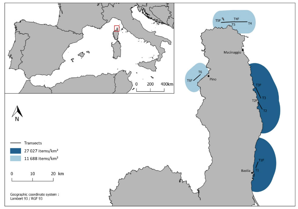
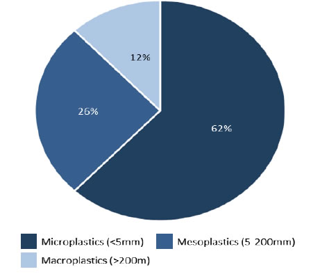
Abundance, Composition and Spatial Distribution of Marine Plastic Litter in Sea Surface Waters Around Cap Corse

DOI: 10.31038/NAMS.2020312

Abstract

Marine litter is a widespread problem affecting all the oceans of the world. Plastics represent around 90% of marine litter, and it is estimated that there are between 15 and 51 trillion plastic particles floating on the surface of the oceans. The objectives of this study are to: (i) identify and characterize the main categories of floating items sampled in surface waters off the Cap Corse peninsula, (ii) provide estimates of the occurrence of floating items in this area, and (iii) get an overview of the potential areas of litter accumulation. We highlighted a heterogeneous distribution of floating litter as the plastic density characterizing the area between Bastia and Macinaggio (27 027 items/km2) was, on average, 2.31 times higher than the density estimated between Macinaggio and Pino (11 688 items.km2). Several studies highlighted that spatio-temporal variability of plastic densities and sizes of plastics (micro, meso, macroplastics) could be tightly linked with hydrodynamics and wind regime, distance to land, coastal human population and maritime traffic. Beyond the need to further raise awareness, providing more evidences and information regarding such marine pollution may hopefully foster urgent management strategies, whereby the most effective mitigation strategy implies reducing the input at its source.

Keywords

Plastic, marine litter, manta-net, Mediterranean Sea.

Introduction

Marine litter is a widespread problem affecting all the oceans of the world. Plastic pollution has gained attention by scientists and public perception in the last decade [1, 2]. Plastics represent around 90% of marine litter [3], and it is estimated that there are between 15 and 51 trillion plastic particles floating on the surface of the oceans [4].Global plastic production increased from 5 million tonnes in 1950 to 322 million tonnes in 2015 [5] It is considered that, on average, around 80–90% of ocean plastic comes from land-based sources, including via rivers, with a smaller proportion arising from ocean-based sources such as fisheries, ships and aquaculture. Plastic inputs from land to ocean was estimated to represent at least 4.8 to 12.7 million tonnes in the year 2010 [6]. Because of their abundance, durability and persistence, marine plastics constitute today a major threat to the marine environment [7].

The most visible impacts of marine plastics are the ingestion, suffocation and entanglement of hundreds of marine species, including species listed on the IUCN Red List as near threatened or above [8]. Microplastics (less than 5 mm in diameter), in particular, have recently become a source of concern, as their ingestion has been observed in a wide variety of taxa including zooplankton, marine invertebrates, fish, turtles, seabirds, and marine mammals [9–11]. Once ingested, microplastics can cause starvation, alterations in intestinal functions, a reduction in feeding capacity, energy reserves and reproductive output [12]. Also, contaminated preys can be consumed by predators leading to the transfer of plastics accross trophic levels [13]. Moreover plastics are polymers that may contain a large variety of chemical additives and contaminants, including organic pollutants and endocrine disruptors, that pollute the environment [14] and can be harmful to marine biota [15, 16].

Floating marine litter also plays an important role in the spread of marine or terrestrial organisms, including the dispersal of invasive species that may pose a threat to local ecosystems [17]. Also, the hydrophobic nature of plastics stimulates the formation of biofilms and allows the establishment of numerous organisms, called “epiplastic” organisms, which constitute a new marine ecosystem called “plastisphere”[18]. It can host different groups, in particular microbial organismsincluding pathogenic viruses or bacteria but also fungi, algae, molluscs, cnidarians, and crustaceans [19–21]. The surge in the number of litter introduced into the marine environment currently offers a great variability of objects that may serve as « novel habitat » or as « hitch-hiking raft »  [22, 23].

In addition to causing harm and threatening marine ecosystems, marine litter, especially plastic, can also negatively affect human wellbeing, food security and socioeconomic sectors such as tourism, aquaculture, fishing and navigation [24-26].

The Mediterranean Sea is considered as a biodiversity hotspot [27], besieged by multiple human pressures. Indeed, its shores are home to around 10% of the world’s coastal population and around 100 million people live within 10 km of the coast [28]. Moreover, the Mediterranean basin is one of the busiest shipping routes in the world and receives the waters of densely populated watersheds, e.g. the Nile, the Ebro, the Po [29]. It is therefore not surprising that the basin is nowadays described as one of the areas most affected by marine litter in the world, whereby the average density of plastic as well as its frequency of occurrence throughout the basin were comparable to accumulation zones in ocean gyres [29–31]. In Europe, various regulatory directives have been put in place to limit and reduce this pollution, such as the Marine Strategy Framework Directive (MSFD). In order to define the concept of « Good Environmental Status », the MSFD proposed 11 descriptors including descriptor n° 10 describing good status for marine litter as follows: “Properties and quantities of marine litter do not cause harm to the coastal and marine environment” [32]. Also new knowledge on this topic may have impact in the implementation of other environmental regulations such as the new European Strategy for Plastics in a Circular Economy (COM/ 2018/028 final), which has recently agreed on banning certain single use plastic (SUP) items.

To develop and validate indices of ecosystem status or pollution, it is necessary to have access to areas with low human impact and then validate them along local pressure gradients [33]. Corsica, is a privileged area in the North-Western Mediterranean. It is at the centre of one of the most touristic regions in the world still sheltered from heavy pollution of anthropic origin. This area should come closer to the concept of Good Ecological Status in terms of pollution by plastic marine litter. Our study intends to provide further information on marine litter regarding the northeastern waters of Corsica, part of the Cap Corse and Agriate Marine Natural Park (PNMCCA). This area is also comprised within the Pelagos Sanctuary, a large marine area subject to an agreement between Italy, Monaco and France for the protection of marine mammals.

In detail, the objectives of this study are to: (i) identify and characterize the main categories of floating items sampled in surface waters off the Cap Corse peninsula, (ii) provide estimates of the occurrence of floating items in this area, and (iii) get an overview of the potential areas of litter accumulation.

Material and method

In August 2019, the Corsican Blue Project team carried out a marine litter sampling campaign  within the perimeter of the Cap Corse and Agriate Marine Natural Park (PNMCCA). A total of six manta-net tows were conducted along the coast of the Cap Corse peninsula between Bastia and Pino, including three transects along the eastern coast (Bastia-Macinaggio) and three transects along the northwestern coast (Pino-Macinaggio). The manta-net, characterized by a rectangular opening of 86 x 46 cm and a net opening of 330 μm, was deployed at the surface beyond the boats’ wake at an average speed of 2.2 to 2.4 knots and for about 30 min per tow. General characteristics of each transect were recorded. After each sampling, the entire net was thoroughly rinsed with seawater from the opening to the collection bag to ensure that all the debris were concentrated in the cod end before being retrieved.

Collected samples were sent for analysis to the STARESO (STAtion de REcherches Sous-marines et Océanographique) research station.In the laboratory, the samples were rinsed with seawater on a 300 μm sieve.Then the mesh was rinsed with tap water and the sample was collected. Sampling consists of direct extraction from the environment of items that are recognizable by the naked eye. Several steps have been taken to separate the litter from the biological matrix and water [34]. Litter was manually separated from natural debris by removing the largest pieces of biological material (leaves, algae, wood …) and rinsing them with water that underwent a second sorting to avoid any loss of debris [35]. Items that were visually identified as litter were collected using fine forceps and then counted. To avoid misidentification and underestimation of microplastics it is necessary to standardize the plastic particle selection, following certain criteria to guarantee proper identification [34]. Plastics were identified according morphological characteristics and physical response features (e.g. response to physical stress; microplastics were bendable or soft, colors) [34, 36]. Identified plastic items were measured over their largest cross-section (total length) in order to be classified into three categories: microplastics (<5 mm), mesoplastics (5-200 mm) and macroplastics (> 200 mm) [37]. Plastic items were also classified, as proposed by [21], into six categories according to their visual characteristics:

1. Fragment: this category is generally the most abundant. They are rigid, thick, with sharp, pointed edges and an irregular shape. They can be of different colors.

2. Film: they also appear in irregular shapes, but compared to the fragments, they are fine and flexible and generally transparent.

3. Pellet: they are generally from the plastics industry. These are irregular round shapes, about 5 mm in diameter. They are generally flat on one side and can be of different colors.

4. Granule: they have a regular round shape and generally smaller, around 1 mm in diameter. They appear in natural colors (white, beige, brown).

5. Filament: these are, with the fragments, the most abundant type of particles. They can be short or long, with different thicknesses and colors.

6. Foam: they most often come from large particles of polystyrene foam. They have a soft, irregular shape and are white to yellow in color.

The surface of the surveyed area was estimated by multiplying the observation width by the transect distance, and litter density (items/km2) was calculated by dividing the items count with the surveyed area surface [29].

Results and discussion

In this study, plastic litter was encountered in 100% of the hauls made off Cap Corse, representing a total of 238 itemsand a mean density of 19357 items/ km2.

We highlighted a heterogeneous distribution of floating litter as the plastic density characterizing the area between Bastia and Macinaggio (27 027 items/km2) was, on average, 2.31 times higher than the density estimated between Macinaggio and Pino (11 688 items.km2) (Fig.1). Several studies highlighted that spatio-temporal variability of plastic densities and sizes of plastics (micro, meso, macroplastics)could be tightly linked withhydrodynamics and wind regime [31, 38], distance to land [29, 39], coastal human population [40, 41] and maritime traffic [23]. In our case, the difference in densities found between the regions Bastia-Macinaggio and Macinaggio-Pino, could be consistent with coastal human population pressurewhereby the area with an estimated higher density is located close to Bastia, a city of more than 44 000 inhabitants.As an example, a sampling campaign conducted in the Ligurian Sea, mainly along the French continental coast, reported that highest densities were found in front of Nice [40]. Corsica has been identified as a reference area where contamination by microplastics was lower compared to other regions off the French Mediterranean coasts (e.g. Antibes, Marseille, Toulon) [42].

NAMS-3-1-304-g001

Figure 1. Average concentration of plastic litter, expressed as debrits per km2, in surface water off Cap Corse.

Moreover, the area between Corsica and Elba has been identified as displaying the highest natural marine debris concentration throughout the Central Western Mediterranean, suggesting therefore that the area is under great influence of terrigenous input [43]. However, the identification of the source of the collected litter remains challenging without the consideration of dispersion models, and items being subject to surface water circulation [44] may drift from their source of input. Indeed, studies investigating on debris transport and dispersion due to marine circulation strongly suggest that floating litter might drift during periods ranging from a few weeks to several years before eventually sinking or beaching [45]. Taking into account thatthe Tyrrhenian Sea has been identified as an important accumulation zone [23] and that the eastern coast of Corsica  is under the influence of the Tyrrhenian sea current which flows along the Italian coast before entering the Corsica channel [46] it is very likely that the area between Bastia and Macinaggiois supplied by debris drifting northwards.

It remains particularly challenging to compare our litter concentrations with those reported inother studies given the large variety of sampling methodologies. However, based on the same sampling methodology, sampled in the northern coast of Corsica, at the same season and at a rather similar distance to land, and concentrations were found to be in a same order of magnitude, ranging from tens of thousands to hundreds of thousands of items per square kilometer [30, 31, 40] (Table 1). However, in our case, densitieswere overall lower, andhigherdensities in the Bay of Calvi might be linked tothe different demographic pressures. Indeed, during summer season, population in Calvi may rise up to 60 000 inhabitants while the northwestern part of Cap Corse does not have such large population centre. However, these densities might also be linked to thedifference inwind stress during the sampling campaign [38], and also, as previously mentionned, to the water circulation properties of the considered coastal areas.

Table 1. Literature data on floating plastic densities for stations along the northen Corsican coast.

Site (NorthernCorsica)

Method

Mesh size (µm)

Density
(items / km2)

Source

Calvi

Manta trawl

333

400 000

[30]

Cap Corse

80 000

Cap Corse

40 000 – 80 000

[31]

Calvi

20 000 – 150 000

[40]

Regarding size classes, 62% of the total number of items was smaller than 5mm (microplastics), 26% measured between 5 and 200mm (mesoplastics), and 12% was bigger than 200mm (macroplastics) (Fig.2). In other words microplastics were 2.4 times more abundant than mesoplastics,and 5.3 times more abundant than macroplastics (> 200 mm).Such proportion is very similar to the study carried out in the Bay of Calvi, reporting that microplastics, mesoplastics and macroplastics accounted for 54%, 28% and 18% of total collected items, respectively [38].

NAMS-3-1-304-g002

Figure 2. Size class of the litter found during the sampling campaign.

Beyond the size-based classification,items were additionnaly classified according to their shape and appearance and it was found that fragments were largely predominant (62%), followed by films (26%), filaments (9%), foams (2%) and pellets (1%) (Fig.3). No granule was found. Such proportion is consistent with previous results reported [39] and it was highlighted that the proportion of fragments was especially important in the north of Corsica compared to other stations throughout the Western Mediterranean Sea [31].

NAMS-3-1-304-g003

Figure 3. Main categories of litter found during the sampling campaign.

While on land, the island of Corsica is currently facing a major litter crisis,  due to overloaded garbage dumps, its coastal marine waters are not exempted from marine litter pollution. In this context and despite a relatively small sampling effort compared to other major sea campaigns, our study provides information regarding the type and occurrence of marine litter and plastics in the local coastal waters off the Cap Corse peninsula. While the average density and types of litter items were in agreement with other comparable studies, we highlighted a potential heterogeneous distribution within the Cap Corse marine waters, with higher densities found in the transects of the eastern coast than in those from the northwestern area of the peninsula. To this, different explanations were proposed, such as terrestrial inputs and the influence of large population centres or the influx of debris through the marine circulation and wind forcing.

Conclusion

We highly advise further marine litter sampling campaigns to be conducted within these waters that are positionned at a bio-geogaphical crossroad where several major currents meet. Moreover such study would be scientifically supported and potentially technically facilitated given the fact that the Cap Corse waters are included within the Cap Corse and Agriate Marine Natural Park and the Pelagos Sanctuary. Field information could, for example, be useful in the risk assessment of whale or mammals exposure to microplastics by validating simulated plastic distribution, in parallel to whale habitat models [47]. Moreover, Corsica is also subject to high tourist flows during summer which also translates into an increment of boating, maritime shipping and passengers transport. It would therefore be advisable to conduct sampling all year round, to highlight any annual variability. This study also intends to promote and encourage further « participatory sciences » by which citizens are involved in data collection, in association with the scientific world.

Beyond the need to further raise awareness, providing more evidences and information regarding such marine pollution may hopefully foster urgent management strategies, whereby the most effective mitigation strategy implies reducing the input at its source.

Acknowledgments

This research was funded by the “Agence de l’eau Rhône Méditerranée Corse” and the “Collectivité de Corse” (CdC), as part of the STARE CAPMED project research.

References

  1. De-la-Torre GE (2019) Microplastics: an emerging threat to food security and human health. J Food Sci Technol.
  2. Gabriel EnriqueDe-la-Torrea, Diana CarolinaDioses-Salinas, JasminMarlithCastro, RosabelAntay, NaomyYupanquiFernández, et al (2020) Abundance and distribution of microplastics on sandy beaches of Lima, Peru. Marine Pollution Bulletin 151:110877.
  3. Laurent C.M.Lebreton, Joost van der Zwet, Jan-Willem Damsteeg, Boyan Slat, Anthony Andrady, et al (2017) River plastic emissions to the world’s oceans. Nat Commun 8:15611.
  4. Van Sebille E, Wilcox C, Lebreton L,Maximenko N, Denise Hardesty B, et al (2015) A global inventory of small floating plastic debris. Environ Res Lett 10:124006.
  5. PlasticsEurope E (2016) Plastics-the facts 2016. An analysis of European plastics production, demand and waste data. Brussels Belgium.
  6. Jambeck JR, Geyer R, Wilcox C,Theodore Siegler R, Perryman M, et al (2015) Plastic waste inputs from land into the ocean. Science 347: 768-771.
  7. Gregory MR (2009) Environmental implications of plastic debris in marine settings—entanglement, ingestion, smothering, hangers-on, hitch-hiking and alien invasions. Philosophical Transactions of the Royal Society B.Biological Sciences 364: 2013-2025.
  8. Gall SC, Thompson RC (2015) The impact of debris on marine life. Marine pollution bulletin 92: 170-179.
  9. Amélineau F, Bonnet D, Heitz O, Mortreux V, Harding AMA, et al (2016) Microplastic pollution in the Greenland Sea: Background levels and selective contamination of planktivorous diving seabirds. Environmental Pollution 219: 1131-1139. [Crossref]
  10. Duncan EM, Broderick AC, Fuller WJ,Galloway ST, Godfrey HM,et al (2019) Microplastic ingestion ubiquitous in marine turtles. Global change biology 25: 744-752.
  11. Lusher AL, Hernandez-Milian G, O’Brien J,Berrow S, O’ Connor I et al (2015) Microplastic and macroplastic ingestion by a deep diving, oceanic cetacean: the True’s beaked whale Mesoplodonmirus. Environmental Pollution 199: 185-191.
  12. Guzzetti E, Sureda A, Tejada S, Faggio C (2018) Microplastic in marine organism: Environmental and toxicological effects. Environmental toxicology and pharmacology 64: 164-171.
  13. Setälä O, Fleming-Lehtinen V, Lehtiniemi M (2014) Ingestion and transfer of microplastics in the planktonic food web.Environmental pollution 185: 77-83.
  14. Gallo F, Fossi C, Weber R, Santillo D, Sousa J, et al (2018) Marine litter plastics and microplastics and their toxic chemicals components: the need for urgent preventive measures. Environmental Sciences Europe 30:13. [Crossref]
  15. Hellmann JJ, Byers JE, Bierwagen BG, Dukes JS (2008) Five Potential Consequences of Climate Change for Invasive Species. Conservation Biology 22: 534-543. [Crossref]
  16. Orsi AH, Whitworth III T, NowlinJr WD (1995) On the meridional extent and fronts of the Antarctic Circumpolar Current. Deep Sea Research Part I: Oceanographic Research Papers 42: 641-673.
  17. Miralles L, Gomez-Agenjo M, Rayon-Viña F, Gyraite G, Garcia-Vazquez E (2018) Alert calling in port areas: Marine litter as possible secondary dispersal vector for hitchhiking invasive species. Journal for Nature Conservation 42: 12-18.
  18. Zettler ER, Mincer TJ, Amaral-Zettler LA (2013) Life in the “Plastisphere”: Microbial Communities on Plastic Marine Debris. Environ SciTechnol 47: 7137-7146.
  19. Quero GM, Luna GM (2017) Surfing and dining on the “plastisphere”: Microbial life on plastic marine debris. Advances in Oceanography and Limnology.
  20. Reisser J, Shaw J, Hallegraeff G,Proietti M, David Barnes KA, et al (2014) Millimeter-Sized Marine Plastics: A New Pelagic Habitat for Microorganisms and Invertebrates. PLoS ONE 9.
  21. Viršek M, Palatinus A, Koren Š, Peterlin M, Horvat P,et al (2016) Protocol for Microplastics Sampling on the Sea Surface and Sample Analysis. JoVE 16: 118.[Crossref]
  22. Aliani S, Molcard A (2003) Hitch-hiking on floating marine debris: macrobenthic species in the Western Mediterranean Sea. Hydrobiologia 503: 59-67.
  23. Mansui J (2015) Observation etmodélisation des macro-déchets en merMéditerranée, de la large échelle aux échellescôtière et littorale.
  24. Rochman CM, Browne MA, Halpern BS, Hentschel BT, Hoh E, et al (2013) Classify plastic waste as hazardous. Nature 494: 169-171.
  25. Sheavly SB, Register KM (2007) Marine debris & plastics: environmental concerns, sources, impacts and solutions. Journal of Polymers and the Environment 15: 301-305.
  26. Werner S, Budziak A, Van Franeker JA, GALGANI Francois, HANKE Georg, et al (2016) Harm caused by marine litter.
  27. Giorgi F (2006) Climate change hot‐spots. Geophysical research letters 33.
  28. Richards LM (2008) CIESIN, Center for International Earth Science Information Network at Columbia University. Reference Reviews.
  29. Cózar A, Sanz-Martín M, Martí E, Ignacio González-Gordillo J, Bárbara Ubeda, et al (2015) Plastic accumulation in the Mediterranean Sea. PLoS One 10.
  30. Amandine Collignon, Jean-Henri Hecq, François Glagani, Pierre Voisin, France Collard, et al (2012) Neustonicmicroplastic and zooplankton in the North Western Mediterranean Sea. Marine pollution bulletin 64: 861-864.
  31. Faure F, Saini C, Potter G, Galgani F, de Alencastro LF, et al (2015) An evaluation of surface micro-and mesoplastic pollution in pelagic ecosystems of the Western Mediterranean Sea. Environmental Science and Pollution Research 22: 12190-12197. [Crossref]
  32. EU Commission (2010) On criteria and methodological standards on good environmental status of marine waters. Official Journal of the European Union, L 232: 14-24.
  33. Gobert S, Richir J (2019) Des indices pour la définition de l’état des masses d’eau en milieu marin: mises au point, applications et aide à la gestion. Geo-Eco-Trop 353-364.
  34. Hidalgo-Ruz V, Gutow L, Thompson RC, Thiel M (2012) Microplastics in the Marine Environment: A Review of the Methods Used for Identification and Quantification. Environ SciTechnol 46: 3060-3075.
  35. Herrera A, Garrido-Amador P, Martínez I,María Dolores Samper, Juan López-Martínez, et al (2018) Novel methodology to isolate microplastics from vegetal-rich samples. Marine pollution bulletin 129:61-69.
  36. Desforges J-PW, Galbraith M, Dangerfield N, Ross PS (2014) Widespread distribution of microplastics in subsurface seawater in the NE Pacific Ocean. Marine Pollution Bulletin 79: 94-99.
  37. Ana LacerdaLdF, Rodrigues lds, Erik van Sebille, Fábio Rodrigues L, LourençoRibeiro, et al (2019) Plastics in sea surface waters around the Antarctic Peninsula. Scientific reports 9:1-12.
  38. Collignon A, Hecq J-H, Galgani F, et al (2014) Annual variation in neustonic micro-and meso-plastic particles and zooplankton in the Bay of Calvi (Mediterranean–Corsica). Marine Pollution Bulletin 79: 293-298.
  39. Zeri C, Adamopoulou A, Varezić DB,Fortibuoni T, KovačViršek M, et al (2018) Floating plastics in Adriatic waters (Mediterranean Sea): From the macro-to the micro-scale. Marine pollution bulletin 136:341-350.
  40. Pedrotti ML, Petit S, Elineau A,Bruzaud S, Crebessa JC, et al (2016) Changes in the floating plastic pollution of the Mediterranean Sea in relation to the distance to land. PloS one 11.
  41. Ruiz-Orejón LF, Sardá R, Ramis-Pujol J (2016) Floating plastic debris in the Central and Western Mediterranean Sea. Marine Environmental Research 120: 136-144. [Crossref]
  42. Gérigny O, Maryvonne H, Tomasino C, Galgani F (2018) Rapport IndicateurMicroplastiquesdans le cadre des campagnes Directive Cadre Eau MéditerranéeOccidentale (DCE) 2018.
  43. Suaria G, Aliani S (2014) Floating debris in the Mediterranean Sea. Marine Pollution Bulletin 86: 494-504.
  44. Millot C, Taupier-Letage I (2005) Circulation in the Mediterranean sea. The Mediterranean Sea29-66.
  45. Zambianchi E, Trani M, Falco P (2017) Lagrangian transport of marine litter in the Mediterranean Sea. Frontiers in Environmental Science 5:5.
  46. Gerigny O (2010) Hydrologieethydrodynamismedans les bouches de Bonifacio: mesures in-situ, modélisation, influence sur la biomasse. 441.
  47. Fossi MC, Romeo T, Baini M,Cristina Panti, LetiziaMarsili, et al (2017) Plastic debris occurrence, convergence areas and fin whales feeding ground in the Mediterranean marine protected area Pelagos sanctuary: A modeling approach. Frontiers in Marine Science 4:167.

Treatment and Management in the Corona Virus Crisis: Think outside the Box While inside the Box

DOI: 10.31038/IDT.2020112

Perspective

I wrote this position paper as someone who wears several hats, each one separately, and primarily, onehat on top of the other. My many personal, family-community, and professional roles overlap and enhanceeach other. In this periodof crisis and challenge, of many difficulties and struggles,new knowledge and new experiences accumulate. In this text, I have chosen to share my personal message, comingfrom weeks of quarantine, and mydiscovery ofadministrative and professional modes of action that were new to me.

In ordinary times, which characteristically have greater degrees of freedom, we often encounter an avoidance approach tochange.The necessary experimentation with unfamiliar modalities/ techniques may even threaten our routine. However, in the face of another reality, there is an opportunity to grow and expand, precisely from a narrow and restricted physical boundary. I found myself in this time in therapeutic and administrative work at the Feeding Clinic, charting new ways andunfamiliar tracks. The deliberations and questionsand observations following my own process are presented below.

From protocol to practice

Protocol is formulatedin routine times, shaped by habits and consistency and based on personal and collective knowledge and experience. These are accompanied by a familiar reality, which at times is nottaken into account.The relevance of accepted practicesdiminishes in times of crisis. Work protocols that have served us well until now require renewal and change, according to the given needs.

We naturally tend to prefer familiar treatment plans and methods, thinking that they will achieve optimal results. However, relianceon conventionalapproaches can lead to missed therapeutic and administrative opportunities that are appropriate for these periods of crisis. As we become more creative and liberated from therapeutic conventions, we can achieve a broad and refreshing newreality-based therapeutic practice. For example, telephone or e-mailsduring the corona crisis can provide a reframing of the situation as well as a calmresponse and guidance on the challenge at hand.

Online treatment and management

The interpersonal encounter is a basic component of therapeutic work in the field of early childhood mental health. The session includes eye contact in which the therapist observes emotional states and the quality of the interaction, based on mimicry and body language. The encounter sometimes invites physical contact .Treatmentina period of quarantine eliminates some elements of nonverbal communication but may well sharpen other therapeutic skills.

The richness and diversity of online treatment depends on the technological means and skills of both the therapist andthe family in treatment. The quality of the therapy is also affected by the economic level and accessible material, which isexpensive. A flexible and open approachmakes remote communication with diverse populations possible and is combined withsensitivityto the populations’ unique character and needs.

The advantages of remote support are both technical, such as a high level of accessibility, and qualitative. For example, in a phone conversation with parents, sensitive and attentive listening can compensate for the lack of eye contact whileways to introduce new foods to a picky eater are presented.

Intake as a diagnostic and therapeutic tool

The face-to-face intake is currently replaced by telephone intake. Many new applicants experiencea high level of distress.In many cases, it is my professionalresponsibility to refer callers to emergency medical centers after consulting with the physician in the community.

Telephone intake for non-urgent callers is usually necessaryfor parents waiting for their children’s acceptance tothe feeding center. The intake is primarily intended to address their feelings of anger, frustration and disappointment. These intense emotions are not necessarily related to the child’s medical condition, and often reflect the parents’ cognitive and emotional state and need for an attentive ear, with or without eye contact.

Anxiety vs. Distress

Parents turn to a feeding center with possible distress in the background. How threatening or disruptive the situation is will affect the situation, as well as the parental resources that are mobilized. Currently, as the level of collective anxiety rises, the internal and private threat is sometimes temporarily reduced. Accordingly, and also because of the life-threatening possibility of increased exposure to Covid-19 virusin the medical center, parents refrain from contacting us unless there isimmediate danger.As therapeutic alternatives are developed; we bolster the parents’ confidence who willthen appreciate conventional therapy when it becomes possible .

Creativity and Productivity

While curiosity is the primary driving force when seeking therapeutic solutions, creativity is the fuel for finding the therapeutic path. There are different examples. For instance, a toddler was initially described on the phone, as refusing to eat. He achieved independent eating and avaried dietafter one therapy (phone) call, which came after a consultation and preliminary information from the educational and rehabilitation staff of the daycare center he attended prior to quarantine with his family.

Thinking outside the box, while being physically inside the box of my home, and physically distant from the patient and his family, led me to enlist family members as modelsfor social eating. The patient’s achievement delighted all those who saw themselves, and rightly so, as partners in his success.

Multidisciplinary team

The uniqueness of our feeding center is the skilled, sensitive, multidisciplinary response that can be individualized and family-oriented under one umbrella. Our staff support and complement each other so that the whole is worth more than the sum ofits parts. At this time, this integrative work continues, in shared thinking and discussion and supportive, encouraging conversations, with the hope of resuming non-virtual work sessions, as the danger passes.

Unpaid leave, layoffs and a reduced workforce at the feeding clinic as in other medical and treatment centers, arevague, unresolved, but solvable. I leave issues to the experts in economics, with the challenge of translating unique therapeutic productivity into the materialworld.

“Talk. Share. Work on youemotionally and psychologically, now is the time.” Dr. Guy Winch believes that the real threat during the Corona virus’s active period is mental. In an article in the Haaretzsupplement (Ayelet Shani, April 10, 2020), he emphasizes the importance of strengthening our coping tools and recommends that the mental health community not give in to helplessness oravoidance.

The routine of our lives can bring calm and stability, based on familiar and fixed events, their high predictability, clarity and logic. When I realized that the Corona virus had entered my personal and professional life, and might rob me of a stable routine, I understood theneed for a response anchored in the new reality.

This understanding led toa therapeutic thought process using methods nottypically included in early childhood mental health. The new reality has also sharpened my understanding of unique ways of managing and maintaining workrelationshipsin my work as coordinator of a multidisciplinary therapy center.

The work methods described above, adapted to extraordinary disruption, are also important for a promptresponse to non-urgent inquiries. Other cases are currently referred to emergency medical units, according to need and the recommendation of community doctors.

I warmly embrace the recommendation of psychologist Dr. Guy Winch. I do not succumb to helplessness . I invite in energized thinking and shared action in the current situation and believe that new insights are beginning to emerge.

Evolution of COVID-19 in Italy, Spain, United Kingdom and the United States

DOI: 10.31038/IDT.2020111

Abstract

This paper aims to help the authorities but especially the EU / EEA public health authorities in monitoring and managing the COVID-19 pandemic. The study provides concrete data on up-to-date and future developments in different countries and territories. The best results can be analyzed and pharmaceutical measures can be implemented in other countries. Thus, in order to have a clear picture of the danger of COVID-19, we studied a possible method of calculating the death rate among the positively confirmed cases. Thus, we have developed different equations, specific for each country, with which we can calculate the death rate. For example, for cases up to 19.03., For Italy, the death rate after 9 days was 25.58170% (9136 deaths / 28.03.) practically and theoretically 24.8% (8857 deaths); for cases up to the date of 4.04. the death rate at a minimum of 9 days was 16.6081% (19901 deaths / 13.04.) practically and theoretically 16% (19172 deaths); for the date of 19.04. the death rate will theoretically be 16.49187% and 23686 deaths, ie from 14.04. by including 19.04 there will probably be 3785 deaths. The method can be used for Italy, Spain and United States of America or other countries. The advantage of this method is that it is specific to each country. It helps us to have an overview and correlating with the number of tests and the age of the patients to choose the best treatments.

Keywords

Cases Italy, Spain, United Kingdom, United States of America deaths COVID.

Introduction

If we consider the total number of cases, 147577 and the number of deaths, 18851, from Italy until April 11, according to https://www.ecdc.europa.eu/en/cases-2019-ncov-eueea then we can say that the death rate increased from 9.50% to 12.77% compared to March 24. But considering that death usually occurs after 14 days, then we can say that this calculation is wrong [1-4].

Using the available preliminary data, the average time from onset to clinical recovery for mild cases is approximately 2 weeks and is 3-6 weeks for patients with severe or critical illness. Preliminary data suggest that patients develop severe disease symptoms, including hypoxia, at 1 week. Among patients who have died, the time from onset of symptoms to outcome varies from 2-8 weeks. [5, 6].

This paper aims to help the authorities but especially the EU / EEA public health authorities in monitoring and managing the COVID-19 pandemic. The study provides concrete data on up-to-date and future developments in different countries and territories. The best results can be analyzed and pharmaceutical measures can be implemented in other countries.

From the desire to be well informed and to have a clear picture of the danger of COVID-19, we studied a possible method of calculating the death rate among the positively confirmed cases. Studying the preliminary data available, there is an increase in deaths at nine or eleven days from increases in confirmations.

According to the model in [4, 5, 7] we have redone the graphs overlapping the deaths until 20.03.2020 with the cases until 11.03.2020 for Italy, Spain, United Kingdom and United States of America, different but representative countries and territories, cultures, approaches, behaviors , different equipment. The graphs overlap at 9 or 10 days. Thus, we have developed different equations, specific for each country, with which we can calculate the death rate. The method can be used for Italy, Spain and United States of America or other countries. The advantage of this method is that it is specific to each country. It helps us to have an overview and correlating with the number of tests and the age of the patients to choose the best treatments.

Results and discussions

In the case of Italy, we noticed, on April 11, changes in the data on the official website regarding the days of March 3, 4, 15, 16. The data used in this study are from the official website.

For Italy, there is an increase in deaths nine or eleven days after the confirmation increases. Because of this, we studied the 9-day death rate using the formula below.

Death rate at least 9 days = (total number of deaths day a + 9/ total number of cases day a) * 100.

There is a greater decrease in the death rate corresponding to 21.03 cases. the medical system was probably helped or was effective.

Graphically representing the death rate at a minimum of 9 days, we deduced the corresponding equation. With this equation we can calculate the death rate and the number of deaths 6 days in advance. If we adapt the method for a longer period of time, we will be able to calculate ahead with that interval.

Table 1. Death rate at least 9 days – Italy.

Criterion number
(x)

Date of confirmed cases

Date of deaths

Death rate after 9 days%(y)

1

11.03.

20.03.2020

33.5698

2

13.03.

22.03.

31.9393

3

15.03.

24.03.

28.7233

4

17.03.

26.03.

26.8227

5

19.03.

28.03.

25.5817

6

21.03.

30.03.

22.9280

7

23.03.

1.04.

21.0186

8

25.03.

3.04.

20.1182

9

27.03.

5.04.

19.0739

10

29.03.

7.04.

17.8702

11

31.03.

9.04.

17.3669

12

2.04.

11.04.

17.0483

In the deduced equations x represents Criterion number and y represents the Death rate after 9 days.

Day 11.03 is the 20th day for Italy and for Spain day 13.03 is the 20th day, if we consider the number of consecutive days in which cases were registered.

The death rate after 9 days is higher initially in Spain but falls more than in Italy. The evolution for these countries is encouraging, the major problem being the number of cases.

IDT-1-1-102-g001

Figure 1. Cases and deaths on 11 / 20.03.2020 – Italy. The deaths on 20.03.2020 correspond to the cases from 11.03.2020. x: Criterion number; y: Rate of death %.

Table 2. Death rate at least 9 days – Spain.

Criterion number
(x)

Date of confirmed cases

Date of deaths

Death rate after 9 days %
(y)  

1

11.03.

20.03.

46.7968

2

13.03.

22.03.

44.1558

3

15.03.

24.03.

37.9280

4

17.03.

26.03.

37.3626

5

19.03.

28.03.

35.4184

6

21.03.

30.03.

32.6726

7

23.03.

1.04.

28.6609

8

25.03.

3.04.

25.2136

9

27.03.

5.04.

20.9012

10

29.03.

7.04.

18.0699

11

31.03.

9.04.

17.0843

12

2.04.

11.04.

15.5116

IDT-1-1-102-g002

Figure 2. Cases and deaths on 11 / 20.03.2020 – Spain.. The deaths on 20.03.2020 correspond to the cases from 11.03.2020. x: Criterion number; y: Rate of death %.

Later I studied the situation in the United Kingdom. Initially, the social spacing measures were not applied here. Studying the appropriate United Kingdom charts, we observed correlations between the number of confirmed cases and deaths from 9 to 12 days later. We calculated the death rate 10 days after confirmation.

March 11 is the 19th day in which cases have been registered in the United Kingdom but the 13th in a row, so we can say that the United Kingdom is behind Italy with 6 days. Spain versus Italy with 3 days.Comparing the death rate corresponding to 11.03.For Spain with the day corresponding to 13.03.for the United Kingdom there is a big difference, the latter registering a much lower death rate initially but a later stay.

In this case it is difficult at the moment to elaborate the corresponding equation.

Studying the appropriate graphs United States of America we observed correlations between the number of confirmed cases and deaths from 9 to 12 days later. But more at 11 days. In order to make comparisons I calculated the death rate 10 days after confirmation.

In this case, the most favorable evolution is the United States of America.

If we consider air pollution, according to [8] then the most polluted is the United Kingdom followed by Italy and Spain which have similar and much lower values.

Table 3. Death rate after 9 and 10 days – United Kingdom.

Criterion number
(x)

Date of confirmed cases

Date of death
after 9 days

Date of death
after 10 days

Death rate after 9 days%
(y)  

Death rate after 10 days %
(y) 

1

11.03.

20.03.

21.03.

38.6058

47.4530

2

13.03.

22.03.

23.03.

39.4915

47.6271

3

15.03.

24.03.

25.03.

29.3859

37.0175

4

17.03.

26.03.

27.03.

30.0064

37.4594

5

19.03.

28.03.

29.03.

28.8593

38.7452

6

21.03.

30.03.

31.03.

30.8310

35.3502

7

23.03.

1.04.

2.04.

31.4798

44.5539

8

25.03.

3.04.

4.04.

36.1644

44.6329

9

27.03.

5.04.

6.04.

36.9960

42.3228

10

29.03.

7.04.

8.04.

31.4412

36.0407

11

31.03.

9.04.

10.04.

32.0536

36.0326

12

2.04.

11.04.

12.04.

30.3928

33.5041

IDT-1-1-102-g003

Figure 3. Cases and deaths on 11 / 20.03.2020 United_Kingdom.
a). The deaths from 20.03.2020 correspond to the cases from 11.03.2020.
b). The deaths from 21.03.2020 correspond to the cases from 11.03.2020.

Table 4. Death rate after 9 and 10 days – United States of America.

Criterion number
(x)

Date of confirmed cases

Date of death
after 9 days

Date of death
after 10 days

Death rate after 9 days %
(y)  

Death rate after 10 days %
(y) 

1

11.03.

20.03.

21.03.

14.6341

25.3658

2

13.03.

22.03.

23.03.

20.4449

28.3223

3

15.03.

24.03.

25.03.

19.9932

27.1433

4

17.03.

26.03.

27.03.

22.5273

27.8051

5

19.03.

28.03.

29.03.

18.1306

23.2713

6

21.03.

30.03.

31.03.

12.7853

16.1536

7

23.03.

1.04.

2.04.

11.5860

14.5941

8

25.03.

3.04.

4.04.

10.9594

12.9583

9

27.03.

5.04.

6.04.

9.8859

11.2186

10

29.03.

7.04.

8.04.

8.8148

10.3437

11

31.03.

9.04.

10.04.

9.0007

10.1385

12

2.04.

11.04.

12.04.

8.6641

9.5090

IDT-1-1-102-g004

Figure 4. Cases and deaths on 11 / 20.03.2020 – United States of America.
a). The deaths from 20.03.2020 correspond to the cases from 11.03.2020.
b). The deaths from 21.03.2020 correspond to the cases from 11.03.2020.

Conclusion

We have proposed a possible method of calculating the death rate among the positively confirmed cases.

We have developed different equations, specific for each country, with which we can calculate the death rate. adapt the method for a longer time we will be able to calculate before that time. For example, for cases up to 19.03., for Italy, the death rate was 25.58170% (9136 deaths / 28.03.) practically and theoretically 24.8% (8857 deaths); for cases up to the date of 4.04. the death rate at a minimum after 9 days was 16.6081% (19901 deaths / 13.04.) practically and theoretically 16% (19172 deaths); for the date of 19.04. the death rate will theoretically be 16.49187% and 23686 deaths, ie from 14.04. by including 19.04 there will probably be 3785 deaths. With this equation we can calculate the death rate 3-4 days before and implicitly the number of deaths for the next 4 days. If we adapt the method for a longer period of time we will be able to calculate ahead with that time interval. The method can be used for Italy, Spain and United States of America or other countries.

The advantage of this method is that it is specific to each country. It does not require sophisticated calculations that involve advanced mathematics or special statistical programs. It helps us to have an overview and correlating with the number of tests, comorbidities and the age of the patients the authorities can choose the best treatments.If we consider the particular cases studied in this paper, we can say that: for Italy, there is a greater decrease in the death rate corresponding to the cases 21.03. the medical system was probably helped or was efficient. The death rate is initially higher in Spain, but is lower than in Italy. The evolution for these countries is encouraging, the major problem being the number of cases. Comparison of the corresponding death rate 11.03.for Spain with the corresponding day 13.03. for the United Kingdom there is a big difference, the latter registering a much lower death rate initially, but a later stay.

In this case, the most favorable evolution is in the United States of America.

References

  1. https://www.ecdc.europa.eu/en/cases-2019-ncov-eueea.
  2. Ezekiel JE, Govind Persad JD, Ross Upshur, Beatriz Thome, Michael Parker, et al. (2020) Fair Allocation of Scarce Medical Resources in the Time of Covid-19. The NEW ENGLAND Journal of Medicine. [Crossref]
  3. Pengfei Sun, Xiaosheng Lu, Chao Xu, Wenjuan Sun, Bo Pan (2020) Understanding of COVID‐19 based on current evidence. Journal of Medical Virology. [Crossref]
  4. Dumitraș CA (2020) Warning – Italy mortality of 32.35%. EdituraSfântulNicolae. http://librariascriitorilor.ro/Lectura/Atentie%20Italia%20mortalitate%20%2032,35_/index.html
  5. DumitraşHuţanu CA, Zaharia M, Pintilie O (2013) Quenching of Tryptophan Fluorescence in the Presence of 2, 4-DNP, 2,6-DNP, 2,4-DNA and DNOC and Their Mechanism of Toxicity. Molecules 18: 2266-2280. [Crossref]
  6. Report of the WHO-China Joint Mission on Coronavirus Disease 2019 (COVID-19).
  7. Dumitraş CA (2015) Poluanți majori ai mediului: dinitrofenoli și dinitrofenil eteri, sinteză, caracterizarechimică, activitate biologică, Ed MatrixRom, București.
  8. waqi.info/ro.

CoVid-19 its Impact on Healthcare Workers and the Need for Occupational Healthcare Provision

DOI: 10.31038/IMROJ.2020523


The world woke up in November 2019 [1] to the arrival of a new “enemy” in its parade of infectious pathogens, firstly in China and in an ominous fashion, now across the globe – the coronavirus, named CoVid-19 by the WHO [2,3]. A dreaded new pandemic [4] has now announced its presence, swept through the globe with an unimaginable speed [5] and savagely wreaked havocto healthcare systems, financial sectors and lives [6] across the world.It has disrupted life as we knew it before the crisis, to an extent we have never imagined possible. The magnitude of this disaster and its multifaceted ramifications, together with its speed of spread [5] is a new and novel experience in history. Life cannot be the same again.

The healthcare worker (HCW) has now suddenly been thrown into the frontline of this storm again, battling a terrible new foe that has crossed the paradigm between its natural host to man. Many of us are not prepared for this [7]

The health of the HCW is of paramount importance in this war. The sheer lack of systemic support for the HCW is obvious in many countries. In developing countries, a lack of investment in systemic development, in manpower development, resource allocation, professional recognition and support in Occupational Health will now manifest itself and the price is costly in terms of lives. The ravage to the HCW will translate to lives lost for both the patient and the HCW. The economic impact [8] and cost of this will be in millions of lives impacted or lost [9,10].

“More than 4,000 people have died worldwide [9] reaching 7529 as of 17 Mar 2020 [10] and more than 113,000 cases on 10th Mar 2020 (reaching 184,976 as of 17th Mar 2020) [10], have been confirmed in over 110 countries  [10]. But unfortunately, the economic impacts also have dramatic effects on the wellbeing of families and communities. For vulnerable families, lost income due to an outbreak can translate to spikes in poverty, missed meals for children, and reduced access to healthcare far beyond COVID-19. While the spread in the United States and Europe absorbs much of the media coverage, confirmed cases [9] from Bangladesh to Brazil, from Cameroon to Costa Rica, and in many other low- and middle-income countries mean that many of the economic impacts may affect the world’s most vulnerable populations”[8].

The outcry to develop a robust Occupational Health system that provides guidance tohealth at work [11] in particular in the Healthcare system itself, has now escalated to a scream. Where governmental and private healthcare systems did not and will not invest in this area, a desperate stage will arrive when default or demise from the frontline will lead to massive losses in healthcare provision itself for the population in a crisis. The healthcare workforce can be destitute when it goes into war with an unprepared workforce.

We need to galvanise development in this area at a rapid and sadly, crisis mode if this has not been done previously.  In many countries, Occupational Medical services do not exist. Even in many modern healthcare systems, the presence of a doctor who is trained to look after HCWs within the healthcare system is itself lacking. Circumstances now prove that healthcare provision for the HCW is an essential component of healthcare delivery as it is now being tested to its limits.  Our priorities need to reorganise as we realise that to win this battle, the HCW needs to survive the crisis.

The essentials of a viable Occupational Health Service within the healthcare system fundamentally comprise two critical components – a clinical service and an administrative occupational health governance / policy structure. The latter is often neglected but is essential to provide guidance and drives the priorities of the Occupational Health system. Creating the structures and funding these,providing manpower, training and logistic supportarecritical to our survival in a crisis.

One demonstration of thisgap, that has become obvious even to the public,is the need for respiratory protection and personal protective equipment for the healthcare worker. Respirators and masks have become scarce resources. How many of our HCWs knew the fundamental differences between a mask and a respirator before the crisis?

HCWs can become tired and fatigued. Physical and mental exhaustion can take its toll and superheroes will also die.  How about the families and psychological needs of those that toll?  What is the price for heroes fallen in this travesty? HCWs are human and will also need care. We need to act rapidly. We must not forget that we too, are human.  As my young colleague in the frontline opined, “We also want to live”.

References

  1. First Covid-19 case happened in November, China government records show – report. South Morning China Post, 13th Mar 2020.
  2. What’s in a name? Why WHO’s formal name for the new corona virus disease matters- WHO, 11th Feb 2020
  3. A Joint Statement on Tourism and COVID-19 – UNWTO and WHO Call for Responsibility and Coordination. WHO 27th Feb 2020
  4. Cucinotta D, Vanelli M (2020) WHO announces COVID-19 outbreak a pandemic. Acta Biomed 91:157-160. [crossref]
  5. Wu J, Leung K, Leung GM et al. (2020) Now-casting and forecasting the potential domestic and international spread of the 2019-nCoV outbreak originating in Wuhan, China- a modelling study. The Lancet 395: 689-697.
  6. Weiss P, Murdoch DR (2020) Clinical course and mortality risk of severe CoVid19. Lancet 395:1014-1015. [crossref]
  7. Chaolin Huang, Yeming Wang, Xingwang Li, Ren L, Zhao Jet al. (2020) Clinical features of patients infected with 2019 novel corona virus in Wuhan, China. Lancet 395: 497-506.[crossref]
  8. The Economic Impact of COVID-19 in Low- and Middle-Income Countries. Evans, Over M. Center for Global Development (CDG), USA.  12th Mar 2020.
  9. Corona virus disease 2019 (COVID-19) Situation Report – 50. WHO 10th Mar 2020
  10. Novel Corona virus (COVID-19) Situation WHO 17th Mar 2020
  11. Guidance on Preparing Workplaces for COVID-19. U.S Department of Labour Occupational Safety and Health Administration OSHA 3990-03 2020.

Minimally invasive proximal cavities restored with a hybrid, flowable and low-shrinking composite: effect of marginal ridge preservation on failure pattern

DOI: 10.31038/JDMR.2020314

Abstract

Objectives: The present study assessed the restorative potential of silorane, flowable or hybrid-based composite resin for the ultraconservative occlusal fossa technique.

Materials and methods: Thirty-two intact human molars received in the proximal ridge a 1x2x4 mm size occlusal cavity leaving the enamel ridge intact. The bur was then tilted at 30° alongside enamel ridge to simulate a typical carious cavity. After enamel etching and application of adhesive system, cavities were filled with three composites and then, a 0.8 mm diameter hole was prepared beneath the proximal contact area to simulate an incipient enamel carious lesion. Restored molars were submitted to mechanical loading. The adhesive interfaces before and after loading were evaluated with SEM. The fracture test was performed on fatigued molars and maximum breaking loads were recorded.

Results: The hybrid and silorane composites showed, after the fatigue test, higher percentages of continuous margins (81±12 and 75±17, respectively) in comparison to flowable material (53±24). Similar fracture resistance was recorded by the three composite types, but significantly lower than the fracture resistance of the non-restored group. Nevertheless, a trend to a ductile behaviour, i.e. better capacity for elastic deformation, was observed in the group restored with the hybrid composite.

Conclusions: Minimally invasive occlusal restorations with marginal ridge preservation and simulated proximal decay can be efficiently restored with hybrid and low shrinking composites. The flowable composite might not be indicated in this cavity type, in view of the marginal degradation observed after the fatigue test.

Clinical relevance: The ultraconservative occlusal fossa restorations realized with hybrid composite or silorane, may be a valid alternative to conventional class II restorations.

Keywords

Occlusal fossa technique, modified class II cavities, interproximal carious lesions, minimal invasive, marginal adaptation, resin composite, marginal ridge preservation.

Introduction

For many years, Black’s idea of extension for prevention [1] has been an important principle in dentistry. In this approach, caries lesions are surgically removed and the restorative margins extended to areas enabling an easy cleaning. But in recent years, this idea has been considered outmoded due to an increased understanding of caries process and the development of restorative adhesive materials. A more conservative concept called ‘minimally invasive dentistry’ has been progressively introduced into the dental profession. In this philosophy, the preservation of natural tooth structure is paramount as no actual restorative material can replace enamel and dentine at a hundred percent.

The conventional class II cavity for the treatment of interproximal caries lesions, even if it is a commonly used restorative procedure, is particularly destructive because of the indirect approach to access the lesion. The marginal ridge removal undermines tooth resistance [2] and there is a high risk of iatrogenic damage to adjacent tooth during preparation [3-5]. In addition, the technical difficulties to correctly shape restorations in the proximal region [6] and the large perimeter of the restoration most likely lead to its long-term failure. To avoid these disadvantages, several attempts were made to restore proximal caries lesions.

Remineralization with fluoride and proximal sealing may be the most conservative ways to treat incipient caries or small proximal lesions in combination with limited demineralization areas in the enamel wall in patients with a rather low caries activity [7]. Thanks to a better understanding of the carious process, it is widely accepted that, in many cases, demineralized enamel lesions without cavitation can be remineralized with fluoride [8]. In respect to proximal sealing, this technique consists of the infiltration of a low-viscosity resin into demineralized enamel to reduce microporosities and improve mechanical support [8]. Nevertheless, both techniques, i.e. fluoride application and proximal sealing, are indicated when caries is confined to enamel.

In cases where caries has involved also dentinal tissue, a restorative approach is necessary and several techniques such as minibox, tunnel and ultraconservative occlusal fossa, are currently available. The minibox or vertical slot technique [9], in which the marginal ridge is removed whilst preserving as much tooth tissue as possible, is a more conservative approach than conventional class II cavity. Another attempt to even more conservative approach is the tunnel technique allowing partial preservation of marginal ridge. Nevertheless, none of the suggested conservative intervention modalities gave satisfactory results, especially when glass-ionomer cement was used as restorative material. One review [10] stated that both efficiency in caries removal and marginal ridge strength were reduced in glass-ionomer tunnel restorations with an annual failure rate of 7-10%. Another study [11] found that glass-ionomer tunnel restoration was more damaging than minimal class II composite restoration as evidenced by the stiffness, load at fracture and proximity of the restoration to the pulp.

Finally an ultraconservative occlusal fossa [9,12] or extended sealing [13] technique was suggested in which dentin caries were removed through a small occlusal cavity while preserving the marginal ridge. Other names such as ‘internal preparation’, ‘partial tunnel’, ‘blind tunnel’ and ‘class I tunnel’ have also been used to describe this technique [9]. These procedures avoid the disadvantages of other techniques described above and can be considered the most conservative alternative to conventional class II approach. While some studies observed more risk of failure, mainly due to fracture of the marginal ridge [7,10,11,14], for tunnel or occlusal fossa restorations compared to those of conventional class II, adhesive restorative materials can often re-establish support for fragile enamel marginal ridge [9,15] especially when the proximal carious lesion is more than 2.5 mm below the crest [16]. Moreover, low-shrinkage composite materials might limit weakening of enamel ridge during restorative work due to the generation of lower contraction stresses during polymerization.

Only a few studies evaluated the occlusal fossa procedure [7,17,18] and none of them had the same approach as the present study since they were in-vivo trials and cavities were restored with glass ionomer material. Findings of these studies were very diverse. In-vivo studies reported failure rates of 0 to 10 per cent per year in 2 to 7 years. The comparison of results between tunnel and occlusal fossa restorations was also contradictory; one study reported higher failure rates of occlusal fossa restorations to those of tunnel restorations [18] and another similar study reported the exact contrary [19] but 5 years after, the same author reported that there was no difference in failure rate between two types of restorations [7]. However, it is interesting to see that in the above mentioned limited in-vivo trial with 20 restorations and a mean final assessment time of 23.3 months, no collapse of the marginal ridge was observed while it was thought to be a common occurrence. This fact gives clinical potential to this technique [17]. Another study concluded that maintaining the residual tooth ‘bridge’ in the form of proximal ridge has the potential to limit tooth deformation [20].

For the occlusal fossa procedure, an alternative material to glass ionomer could be resin composites with different mechanical properties (Table 1). Silorane and flowable composite have similar elastic modulus but develop different contraction forces whilst hybrid composite has a higher elastic modulus with contraction forces within the range of the two other materials. All three materials present a high filler load by weight to ensure mechanical strength of the restorations and could be potentially used for the definitive restoration of proximal incipient carious lesions. And given the fact that there is no available technique to reproduce artificial carious lesions through the enamel, in our study the proximal carious lesions were simulated by a cavity, drilled into the proximal wall, as this was the only way to simulate proximal enamel demineralization. This method might demonstrate if restorative procedures with different resin composites are capable to resist fatigue test and provide sufficient mechanical support to the restored teeth, even in cases in which enamel substance is eliminated beneath proximal contact area of the marginal ridge.

Table 1. Material Properties (information provided by manufacturers)

Material

Elastic modulus [GPa]

Filler load by weight [%]

Contraction force [Kg]

Flowable

10.5

81

4.2

Hybrid

22.0

92

2.4

Silorane

11.7

76

1.4

Therefore, the aim of this study was to assess the restorative potential of a silorane, flowable or hybrid-based composite resin for the ultraconservative occlusal fossa technique. The first null hypothesis was that there would be no difference in marginal adaptation amongst molars restored with different materials, before and after cyclic mechanical loading. The second null hypothesis was that there would be no difference in the marginal ridge fracture resistance amongst different experimental groups (molars restored with different materials).

Materials and methods

Thirty-two caries-free human third molars were used for this study and randomly assigned to four equal experimental groups. Group description and material properties are detailed in Tables 1 and 2.

Table 2. Description of experimental groups and materials used

Batch numbers

Flowable

Flowable composite
(Clearfil Majesty™ Flow; Kuraray Medical Inc., Okayama, Japan)

0304BA

Hybrid

Inhomogeneous micro hybrid composite with pre-polymerized
homologous splinters
(Clearfil Majesty™ Posterior; Kuraray Medical Inc., Okayama, Japan)

0006CA

Silorane

Silorane-based composite
(Filtek™ Silorane; 3M ESPE, Seefeld, Germany)

N391668

Control

Natural teeth without any preparation
(Positive control for the fracture strength test)

Adhesive system

Clearfil SE Bond
(Kuraray Medical Inc., Okayama, Japan)
Silorane System Adhesive – Bond, for Silorane group
(Filtek™ Silorane; 3M ESPE, Seefeld, Germany)

041780
N391668

Each tooth received in the proximal ridge an occlusal cavity of dimension 1x2x4mm (Fig. 1a) prepared with a 0.9 mm diameter and 80 µm diamond-coated cylinder bur (Intensiv SA, Grancia, Switzerland) mounted on a red contra-angle handpiece leaving the whole enamel ridge intact. The bur was then tilted at 30° alongside enamel ridge to simulate a typical carious cavity (Fig. 1b). The marginal edge was bevelled with a 25 µm flame-shaped bur (Intensiv SA, Grancia, Switzerland). The cavities were subsequently sealed with a 2-step self-etching adhesive system (Clearfil SE Bond, Kuraray Medical Inc., Okayama, Japan). A 35 % H3PO4 gel was used as an etching agent for 30 s on enamel only and rinsed off with a generous water spray. After careful drying of the cavities with a gentle air spray, the primer was applied for 20 s with a microbrush and gently air-dried. Then the bond was applied for 20 s, gently air-dried and light-cured (Demi plus, 1100 mW/cm2 to 1330 mW/cm2, Kerr Corporation, Orange, USA) for 20 s. For the silorane group, the bond of silorane system adhesive (SSA) was then applied and light-cured (Demi plus, 1100 mW/cm2 to 1330 mW/cm2, Kerr Corporation, Orange, USA) for 20 s to avoid chemical incompatibility between the layer of SE Bond and silorane composite. There are two main reasons for use of the combination SE Bond and bond of SSA; in order to make the comparison of 3 different types of restorations possible, and because the interface primer-bond of SSA have shown nanoleakage in microtensile tests [21,22]. As a result, few attempts have been made to use the methacrylate adhesive for silorane restorations and acceptable results have been obtained when a hydrophobic resin coating layer, i.e. bond of SSA, was placed on top of the methacrylate adhesive layer [23,24,25]. Thus, this method was applied for the silorane group in this study. The cavities were then filled with the restorative materials (a hybrid, flowable and silorane-based composite) in two subsequent layers, light-cured (Demi plus, 1100 mW/cm2 to 1330 mW/cm2, Kerr Corporation, Orange, USA) for 40 s per layer. Finishing and polishing procedures were performed immediately after light curing with a 40 µm point-ended pear bur (Intensiv SA, Grancia, Switzerland) and composite polishing points (Shofu Dental GmbH, Ratingen, Germany) with slight pressure with intermittent water spray under a 10x magnification. Then, to simulate proximal enamel carious lesion, a 0.8 mm diameter hole was prepared with a round bur (Intensiv SA, Grancia, Switzerland) through the enamel just beneath the proximal contact surface area (Fig. 1c). Restored molars were then maintained for 1 week in a moist atmosphere before mechanical loading.

JDMR-3-1-302-g001

Figure 1. Figures of cavity configuration: (a) occlusal view, (b) proximal view, (c) frontal view. Dimensions are in mm.

All restored molars were submitted to 200’000 cycles of mechanical loading. The mechanical function of the device used in this study closely resembles to the one described by Krejci et al [26] (Figure. 2). The loading force generated by solenoids (Magnet AG, Hausen am Albis, Switzerland) was set at 50 N with a 1.5 Hz frequency, following a one-half sine wave curve. The maximal force was attained at the end of a 2.5 mm total course of the solenoid cores (including the first 1 mm free displacement). The restored molars remained immersed in a saline solution, at room temperature, during the entire test course. The position of the artificial cusps in the test chambers of the mechanical fatigue device was adjusted to maintain a 1 mm distance to the core top, allowing a free initial movement. The artificial cusps contacting the restored molars were made of stainless steel, with hardness similar to natural enamel (Vickers hardnesses: enamel = 320-325; Actinit stainless steel = 315). They were positioned to ensure a perpendicular contact with the restorations.

JDMR-3-1-302-g002

Figure 2. Illustration of the mechanical loading device.

Before and after loading, restored molars were cleaned with toothpaste by using a rotating nylon brush and subsequently thoroughly rinsed in tap water. After careful drying, polyvinylsiloxane impressions (President light body, ColtèneWhaledent, Altstätten, Switzerland) were performed. Gold-sputtered resin replicas (Epofix, Struers, Rodrove, Denmark) were fabricated from these impressions and used for a quantitative analysis of the enamel-restoration adhesive interface, using a Scanning Electron Microscope (XL 20, Philips, Eindhoven, The Netherlands). The evaluation was performed at a standard 200x magnification. In order to standardize the assessment, the following parameters were considered: percentages of continuous margins (%CM) and percentages of non-continuous margins (%NCM) either due to the presence of enamel fractures (%NCM EF) or pure gaps (%NCM PG).

The fracture resistance test was performed by using a universal testing machine (Instron, Model 1114, Instron Corp, High Wycombe, Great Britain) on the previously fatigued restored molars. Each tooth was inserted into a custom-made holding device, and a controlled load was applied using a stainless steel rod vertically to the longitudinal axis of the root. Pressure on the tip was applied at a crosshead speed of 1 mm/min applied on the occlusal surface of the marginal ridge. All restored molars were loaded until fracture and the maximum breaking loads were recorded in Newtons (N).

Statistical analysis

All data was statistically evaluated by using SPSS for Macintosh. Differences in fracture strength % of continuous margins, in % of enamel fractures and in % of pure gaps among the 3 groups were tested with ANOVA and Duncan post-hoc test at a level of confidence of 95 %.

Results

The results of marginal adaptation (mean ± standard deviation of %CM, %NCM EF and %NCM PG), both before and after loading, are presented in Table 3.

Table 3. Percentage of Continuous Margins (%CM), of non CM due to the presence of Enamel Fractures (%NCM EF) and of NCM due to the presence of Pure Gaps (%NCM PG) before loading (BL) and after loading (AL).

Groups

%CM
Mean ± SD

%NCM EF
Mean ± SD

%NCM PG
Mean ± SD

BL

AL

BL

AL

BL

AL

Flowable

95 ± 5a

53 ±24b

0a

3 ± 6a

6 ± 5a

41 ± 20c

Hybrid

85 ± 11b

81 ±12a

10 ± 10b

12 ± 9b

2 ± 3a

1 ± 2a

Silorane

95 ± 5a

75 ±17a

1 ± 3a

4 ± 9a

3 ± 3a

18 ± 10b

Numbers designated by different letters are significantly different and apply to each column

Before loading, the groups restored with flowable and silorane composite performed statistically similar and presented significantly higher %CM than the one restored with the hybrid composite.

After loading, the groups restored with silorane and hybrid composite attained statistically similar %CM and were significantly higher than the one restored with the flowable composite. The flowable group attained the lowest %CM.

When comparing the results between intervals before-after loading, the group restored with flowable showed an important decrease of marginal adaptation. In this group, almost 50% of the margins were opened after loading, whereas hybrid group showed only a little decrease of 4.1%.

In respect to the %NCM, enamel fractures were significantly more present in margins of groups restored with the hybrid composite whereas pure gaps were typically observed in groups restored with the flowable and silorane composite.

Representative micrographs of the different marginal characteristics on each group, i.e. continuous margin, para-marginal enamel fracture and pure gaps are shown in Fig. 3.

JDMR-3-1-302-g003

Figure 3. Representative SEM micrographs of restorations’ enamel-composite interface after loading. The arrows indicate: (a) continuous margin, (b) para-marginal enamel fracture, (c) pure gaps. (E=enamel, S=silorane, P=hybrid composite, F=flowable composite).

The means with standard deviations of fracture resistance test on fatigued restored molars, as well as the minimum and maximum forces registered during the fracture test are presented in Table 4. No significant differences in fracture strength were detected between the three restored groups. A significantly higher fracture strength was observed in the non-restored group control, that is, the one in which the marginal ridge was intact.

Table 4. Results of fracture resistance. Mean and SD expressed in Newtons. Minimum and maximum loading forces registered for each group

Groups

Mean ± SD

Minimum

Maximum

Flowable

324 ± 70b

211

402

Hybrid

296 ± 89b

169

398

Silorane

251 ± 93b

76

362

Control (non-restored tooth)

552 ± 111a

358

706

Levels designated by different letters are significantly different and apply to each column

The typical stress-strain curves for brittle and elastic materials [27] were used for comparison with each group during the fracture test, figure 4 (a to d) for the flowable, silorane, hybrid and control group, respectively. It was interesting to see that although no significant differences in fracture strength were observed among the three materials, the shape of the stress-strain curve was specific for each group. The profile of the stress-strain curves in the flowable group (Fig. 4a) evidenced a material poorly ductile (represented by a short length of the horizontal line within the curve which shows that the material can be extended but does not show plastic deformation). A similar behavior was observed in the silorane group (Fig. 4b). Conversely, the curves of the hybrid composite (Fig. 4c) evidenced a slightly more elastic behavior (represented by a long horizontal line within the curve which shows the plastic deformation of the material) before fracturing. Finally, the curve profile of the control group (Fig. 4d) were typical of a stiff material (represented by a steep gradient of the curve) like enamel.

JDMR-3-1-302-g004

Figure 4. Stress-strain curves of the 4 groups.

Discussion

This study was designed to understand how different categories of composite materials, when used in the ultraconservative occlusal fossa cavity, influence the mechanical behavior of these restorations. Its main purpose was to assess which type of material may be most suitable for the minimally invasive restorations of proximal caries. For this purpose, the study design included three materials with different mechanical properties, which would explain the diversity obtained in our results (Table 1). In addition, cavities with a high C-factor were prepared to enable the behavioral comparison of three different materials in extremely difficult conditions concerning contraction stresses. The marginal ridge fracture strength was an important evaluation criteria, especially in comparison with the control group, as it was pointed out to be the main failure cause in occlusal fossa restorations. Nonetheless, the secondary decay and cavitation in enamel were revealed as other principal failure origin in clinical trials [7], therefore the assessment of marginal adaptation before and after mechanical loading was performed as well. The carious lesions were simulated by a cavity which was drilled into the proximal wall. We found that this was the only way to simulate proximal enamel demineralization, given the fact that there is no available technique to reproduce artificial carious lesions through the enamel; a recent study showed that the deepest subsurface lesion produced had a mean depth of 86 micrometer [28].

Marginal adaptation

As statistically significant differences of marginal adaptation rate could be demonstrated between groups, before and after mechanical loading, the first null hypothesis could be rejected. These findings can be explained by differences in the modulus of elasticity (E) and polymerization contraction between materials.

During polymerization, the resin composite contracts and generates stresses at the adhesive interface. These stresses are accompanied by undesirable consequences, such as deformation of the tooth’s cusps, gap formation, and/or para-marginal enamel fractures [29,30]. A stiff restorative material induces more tooth deformation and increases pre-loading stress following polymerization contraction [31,32], which can lead to an immediate margin failure, as it was the case in the hybrid group.

The polymerization contraction undergoes two phases: the phase before and the phase after the gel point. During the first phase, the resin retains its capacity to flow, and therefore, it compensates the contraction forces by rearrangement of the molecules by preventing strain that would otherwise develop at the interfaces [33]. When the gel point is reached, stress is transmitted from the composite toward surrounding bonded structure; the contraction must be compensated by strain of the composite, tooth or adhesive [27]. If the stress surpass the low tensile strength of enamel (10 MPa) [34], para-marginal enamel fracture appears. For reference, the average bond strength is 15-40 MPa [35].

On the contrary, a low-elastic modulus composite, thanks to its elasticity, induces less tooth deformation, thus less pre-loading stress. Reduced E-modulus leads to reduced gap formation [36]. That is why good marginal adaptation could be observed in flowable and silorane groups before loading. Moreover, flowable composites are considered to wet the cavity better than restorative composites due to their flowability, to have thus a better adaptation to the dental surface [37]. And compared to the commercial methacrylate-based composite, the time of gelation of silorane is found to be significantly longer [38]; it decreases the contraction stress and consequently better interfacial integrity scores could be expected [39,40].

As already mentioned, the hybrid composite used in our trial was a stiff material. A higher filler load would lead to an increase in stiffness [41] and generally, it may reduce the overall contraction of composites due to less molecules available for the polymerization reaction [42]. This means, in the contrary, an elastic material like flowable composite would suffer more from polymerization contraction, leading to pre-stressed obturations which allows for more marginal failure under occlusal load [36,43,44]. Moreover, the displacement of cusp under load is inversely proportional to composites’ rigidity [45]. It is in accordance with the results of our trial, where the hybrid group showed better behavior after loading than the flowable group which presented a drastic change. And it should be noted that the silorane group, after loading, had better behavior than the flowable group despite their similar elasticity. Low polymerization contraction of silorane could lead to less pre-stressed obturations than flowable material.

Overall, material chemico-mechanical properties (such as filler/matrix and consequently the material’s elasticity/rigidity and viscosity) proved to influence the marginal adaptation before and after loading, probably because it has impacts on tooth deformation and stress development. And satisfactory initial marginal adaptation didn’t necessarily predict an optimal functional behavior, as shown by the results of flowable group which showed a sufficiently high score in marginal adaptation before loading but incurred a drastic reduction in marginal adaptation after loading. These results are in agreement with a recent review [46]. Elasticity and polymerization contraction have two opposite effects. The benefits of the elasticity of the flowable composite are probably surpassed by its contraction [33]. And at the use of hybrid composite, a certain degree of initial stress should be accepted in order to guarantee sufficient rigidity to the restoration, particularly since para-marginal enamel fractures could present less serious consequences for the longevity of the restorations than pure gaps [32]. According to the literature, there is a general agreement on the fact that a high E-modulus composite (15-20 GPa) would minimize marginal deterioration of restorations under loading and therefore perform well clinically [36,47,48].

Fracture resistance of marginal ridge

The second null hypothesis could be accepted hence no significant differences in fracture strength were noticed within the restored groups, with exception for the group control; it appeared that the marginal ridge strength of restored teeth were significantly reduced in comparison to those of intact teeth. It is difficult to compare these findings with other studies as the experimental set-up in terms of method and materials used are diverse. But considering this fact, abovementioned results are in accordance with Purk’s findings [49] but diverge from other studies where they found no difference in strength of the tunnel prepared and restored teeth and that of sound teeth [8,50-52]. Another author found that a conservative tunnel restoration situated 2 mm from the marginal ridge, does not significantly weaken an otherwise intact tooth [50]. And other researches showed that tooth with tunnel preparation could be reinforced when restored with composite resin, compared to cavity prepared but non restored or cermet restored tooth [49,50].

Given that average masticatory force on a single tooth is 39-146 N depending on the type of food [53-55] and the forces exerted in normal chewing on the occlusal surface seldom exceed 45-60 N [56], mean fracture strength values obtained in all three restored groups showed sufficient reinforcement of resistance to normal masticatory function. Additionally, a study demonstrated that strains in the vicinity of marginal ridges are lower than near the cement-enamel junction, hence the marginal ridges are not highly stressed areas during simulated occlusal loading [57]. The high SD could be explained by the use of non-homogeneous samples, which were natural human teeth. Although each tooth was carefully examined prior to restoration in order to detect enamel fracture lines near to the proximal ridges, variations in tooth morphology like enamel fracture lines might have influenced the results to some extent. Enamel cracks are a regular occurrence in mature human enamel and an experimental study confirmed the importance of margin cracks as a potential source of tooth failure [58].

Despite laboratory testing set-up, investigated samples and experiment protocols could influence the results, in-vitro models allow to test in a controlled way hypotheses that would be unviable to test in-vivo [32]. But these results have to be interpreted with caution due to an extreme cavity design as a “hole” was made in the proximal enamel to simulate demineralization. Possibly, enamel and dentin removal was more pronounced in respect to a real demineralization lesion, and this could have adversely affected the results. This may explain why fracture strength of all restored groups was significantly lower than the non-restored control group. Nevertheless, this “worst case scenario” served to demonstrate that even in cases in which tooth substance is removed below the marginal ridge, restorative procedures with composite are able to provide sufficient reinforcement of restored teeth to normal masticatory function and withstand fatigue test. For example, the hybrid composite used in this study delivered a %CM above 80% after loading, which is considered a sufficiently high score. Additionally, it should be emphasized that marginal integrity and resistance of enamel ridge are not the only parameters implicated in clinical success. Other factors such as retention, marginal and surface discoloration, anatomic form, para-functional forces and secondary caries may influence, clinically, the long-term behavior of this type of restorations. In this sense, future studies should evaluate these parameters on other composite materials than the ones used in this study, to determine if this restorative technique can be validated for clinical use.

Conclusion

Under the conditions of the present in-vitro study, the ultraconservative occlusal fossa technique may be a valid alternative to conventional class II restorations if used after a careful case selection. The first null hypothesis could be rejected; the hybrid composite and silorane material provided the highest percentages of continuous margin after fatigue test. The flowable material produced marginal failures under load, probably due to a lower elastic modulus and a higher contraction force in respect to the other materials. The second null hypothesis could be accepted; while no statistically significant differences in fracture strength were found amongst groups except for control, the hybrid group showed a trend to a slightly more ductile behavior i.e. better capacity for elastic deformation.

References

  1. Black GV (1891) Management of enamel margins. Dent Cosmos 33:85-100.
  2. Reeh ES, Messer HH, Douglas WH (1989) Reduction in tooth stiffness as a result of endodontic and restorative procedures. J Endod 15:512-516. [crossref]
  3. Lussi A, Gygax M (1998) Iatrogenic damage to adjacent teeth during classical approximal box preparation. J Dent 26:435-441. [crossref]
  4. Medeiros VA, Seddon RP (2000) Iatrogenic damage to approximal surfaces in contact with class II restorations. J Dent 28:103-110. [crossref]
  5. Qvist V, Johannessen L, Bruun M (1992) Progression of approximal caries in relation to iatrogenic preparation damage. J Dent Res 71:1370-1373. [crossref]
  6. Gilmore N, Sheiham A (1971) Overhanging dental restorations and peridontal disease. J Periodontol 42:8-12. [crossref]
  7. Hasselrot L (1998) Tunnel restorations in permanent teeth. A 7 year follow up study. Swed Dent J 22:1-7.[crossref]
  8. Kielbassa AM, Müller J, Gernhardt CR (2009) Closing the gap between oral hygiene and minimally invasive dentistry: A review on the resin infiltration technique of incipient (proximal) enamel lesions. Quintessence Int 40:663-681. [crossref]
  9. Tyas MJ, Anusavice KJ, Frencken JE, Mount GJ (2000) Minimal intervention dentistry- a review. Int Dent J 50:1-12. [crossref]
  10. Wiegand A, Attin T (2007) Treatment of proximal caries lesions by tunnel restorations. Dent Mater 23:1461-1467. [crossref]
  11. Papa J, Cain C, Messer HH, Wilson PR (1993) Tunnel restorations versus class II restorations for small proximal lesions: A comparison of tooth strengths. Quintessence Int 24:93-98. [crossref]
  12. Mount GJ (2003) Minimal intervetion dentistry: Rationale of cavity design. Oper Dent 28:92-99. [crossref]
  13. Ardu S, Perroud R, Krejci I (2006) Extended sealing of interproximal caries lesions. Quintessence Int 37:423-427.  [crossref]
  14. Strand GV, Nordbø H, Tveit AB et al (1996) A 3-year clinical study of tunnel restorations. Eur J Oral Sci 104:384-389. [crossref]
  15. Peters MC, McLean ME (2001) Minimally invasive operative care. I. minimal intervention and concepts for minimally invasive cavity preparations. J Adhes Dent 3:7-16. [crossref]
  16. Wilson AD, McLean JW (1988) Glass-ionomer cement. Quintessence Publishing Co, Chicago.
  17. Hunt PR (1984) A modified class II cavity preparation for glass ionomer restorative materials. Quintessence Int 15:1011-1018. [crossref]
  18. Strand GV, Nordbø H, Leirskar J, von der Fehr FR, Eide GE (2000) Tunnel restorations placed in routine practice and observed for 24 to 54 months. Quintessence Int 31:453-460. [crossref]
  19. Hasselrot L (1993) Tunnel restorations. Swed Dent J 17:173-182.
  20. Versluis A, Tantbirojn D, Douglas WH (1998) Do dental composites always shrink toward the light? J Dent Res 77:1435-1445.[crossref]
  21. Mine A, De Munck J, Van Ende A, Cardoso MV, Kuboki T et al. (2010) TEM characterization of a silorane composite bonded to enamel/dentin. Dent Mater 26:524-532.[crossref]
  22. Duarte S, Phark JH, Varjao FM, Sadan A (2009) Nanoleakage, ultramorphological characteristics, and microtensile bond strengths of a new low-shrinkage composite to dentin after artificial aging. Dent Mater 25:589-600.[crossref]
  23. Ivanovas S, Hickel R, Ilie N (2010) How to repair fillings made by silorane-based composites. Clin Oral Invest 16:102-105.
  24. Samimi P, Alizadeh V, Fathpour K, Mazaheri H, Mortazavi V (2016) In-vitro comparison of the effect of different bonding strategies on the micro-shear bond strength of a silorane-based composite resin to dentin. Dent Res J (Isfahan) 13:124-131.[crossref]
  25. Tezvergil-Mutluay A, Lassila LV, Vallittu PK (2008) Incremental layers bonding of silorane composite: The initial bonding properties. J Dent 36:560-563.[crossref]
  26. Krejci I, Reich T, Lutz F, Albertoni M (1990) In-vitro testverfahrenzur evaluation dentalerrestaurationssysteme. SchweizMonatsschrZahnmed 100:953-960. [crossref]
  27. Darvell BW (2009) Materials Science for dentistry, 9th edn. CRC Press, Cambridge, chapter 1, page 16.
  28. Magalhães AC, Moron BM, Comar LP, Wiegand A, Buchalla W et al. (2009) Comparison of cross-sectional hardness and transverse microradiography of artificial carious enamel lesions induced by different demineralising solutions and gels. Caries Res 43:474-483. [crossref]
  29. Ferracane JL (2005) Developing a more complete understanding of stresses produced in dental composites during polymerization. Dent Mater 21:36-42. [crossref]
  30. Garcia-Godoy F, Krämer N, Feilzer A, Frankenberger R (2010) Long-term degradation of enamel and dentin bonds: 6-year results in vitro vs. in vivo. Dent Mater 26:1113-1118. [crossref]
  31. Arola D, Galles LA, Sarubin MF (2001) A comparison of the mechanical behavior of posterior teeth with amalgam and composite MOD restorations. J Dent 29:63-73. [crossref]
  32. Benetti AR, Peutzfeldt A, Lussi A, Flury S (2014) Resin composites: Modulus of elasticity and marginal quality. J Dent 42:1185-1192. [crossref]
  33. Pecie R, Onisor I, Krejci I, Bortolotto T (2013) Marginal adaptation of direct class II composite restorations with different caity liners. Oper Dent 38:E210-220. [crossref]
  34. Bowen RL, Rodriguez MS (1962) Tensile strength and modulus of elasticity of tooth structure and several restorative materials. J Am Dent Assoc 64:378-387. [crossref]
  35. De Munck J, Van Landuyt K, Peumans M, Poitevin A, Lambrechts P et al. (2005) A critical review of the durability of adhesion to tooth tissue: Methods and results. J Dent Res 84:118-132. [crossref]
  36. Asmussen E, Peutzfeldt A (2008) Class I and class II restorations of resin composite: An FE analysis of the influence of modulus of elasticity on stresses generated by occlusal loading. Dent Mater 24:600-605. [crossref]
  37. Chuang SF, Jin YT, Liu JK, Chang CH, Shieh DB (2004) Influence of flowable composite lining thickness on class II composite restorations. Oper Dent 29:301-308. [crossref]
  38. Ilie N, Hickel R (2011) Investigations on a methacrylate-based flowable composite based on SDR™ technology. Dent Mater 27:348-355. [crossref]
  39. Feilzer AJ, De Gee AJ, Davidson CL (1993) Setting stresses in composites for two different curing modes. Dent Mater 9:2-5. [crossref]
  40. Feilzer AJ, De Gee AJ, Davidson CL (1990) Quantitative determination of stress reduction by flow in composite restorations. Dent Mater 6:167-171. [crossref]
  41. Masouras K, Silikas N, Watts DC (2008) Correlation of filler content and elastic properties of resin-composites. Dent Mater 24:932-939. [crossref]
  42. Miyazaki M, Hinoura K, Onose H, Moore BK (1991) Effect of filler content of light-cured composites on bond strength to bovine dentine. J Dent 19:301-303. [crossref]
  43. Ausiello P, Apicella A, Davidson CL, Rengo S (2001) 3D-finite element analyses of cusp movements in a human upper premolar, restored with adhesive resin-based composites. J Biomech 34:1269-1277. [crossref]
  44. Lutz F, Krejci I, Barbakow F (1991) Quality and durability of marginal adaptation in bonded composite restorations. Dent Mater 7:107-113. [crossref]
  45. Ausiello P, Rengo S, Davidson CL, Watts DC (2004) Stress distributions in adhesively cemented ceramic and resin-composite class II inlay restorations: A 3D-FEA study. Dent Mater 20:862-872. [crossref]
  46. Dietschi D, Argente A, Krejci I, Mandikos M (2013) In vitro performance of class I and II composite restorations: A literature review on nondestructive laboratory trials–part II. Oper Dent 38:E182-200. [crossref]
  47. Dietschi D, Argente A, Krejci I, Mandikos M (2013) In vitro performance of class I and II composite restorations: A literature review on nondestructive laboratory trials–part I. Oper Dent 38:E166-181. [crossref]
  48. Lambrechts P, Braem M, Vanherle G (1987) Evaluation of clinical performance for posterior composite resins and dentin adhesives. Oper Dent 12:53-78. [crossref]
  49. Purk JH, Eick JD, Roberts M, Chappell RP, Moore DL (1990) Fracture strength of class I versus class II restored premolars tested at the marginal ridge. 2. cavosurface bonding and cavosurface plus internal enamel bonding. Quintessence Int 21:655-662. [crossref]
  50. Covey D, Schulein TM, Kohout FJ (1989) Marginal ridge strength of restored teeth with modified class II cavity preparations. J Am Dent Assoc 118:199-202. [crossref]
  51. Fasbinder DJ, Davis RD, Burgess JO (1991) Marginal ridge strength in class II tunnel restorations. Am J Dent 4:77-82.[crossref]
  52. Ramírez-Sebastià A, Bortolotto T, Cattani-Lorente M, Giner L, Roig M et al. (2014) Adhesive restoration of anterior endodontically treated teeth: Influence of post length on fracture strength. Clin Oral Investig 18:545-554. [crossref]
  53. Duyck J, Van Oosterwyck H, De Cooman M, Puers R, Vander Sloten J et al. (2000) Three-dimensional force measurements on oral implants: A methodological study. J Oral Rehabil 27:744-753. [crossref]
  54. Howell AH, Brudevold F (1950) Vertical forces used during chewing of food. J Dent Res 29:133-136. [crossref]
  55. Howell AH, Manly RS (1948) An electronic strain gauge for measuring oral forces. J Dent Res 27:705-712.
  56. De Boever JA, McCall WD Jr, Holden S, Ash MM Jr (1978) Functional occlusal forces: An investigation by telemetry. J Prosthet Dent 40:326-333. [crossref]
  57. Palamara JEA, Palamara D, Messer HH (2002) Strains in the marginal ridge during occlusal loading. Aust Dent J 47:218-222. [crossref]
  58. Chai H, Lee JJ, Kwon JY, Lucas PW, Lawn BR (2009) A simple model for enamel fracture from margin crackss. ActaBiomater 5:1663-1667.[crossref]