Abstract
Single point adjustment is the special case in triangulation net adjustment where only the coordinates of one point are unknown. In practice, the coordinates of the points established for densification are calculated in the form of mixed resections. Coordinates of the point to be estimated in mixed resection; It is calculated by taking the average of the coordinates found by the method of projecting more than Intersection and Resection. This solution cannot be said to be suitable for error theory. The solution of the problem in accordance with the error theory is to make adjustment calculations as in all problems with excessive measurements. In single point adjustment, the solution becomes easier if there is no edge measure and the directions are equally weighted. In practice, a single point adjustment calculation is made on the clichés developed for this purpose. In this study, we will show how the single point adjustment can be done according to the least squares (LSQ) theory on a cliché.
Keywords
Intersection, Resection, Single point adjustment, Least square
Introduction
There are explanations for single point adjustment in various sources in the literature [1,2]. But the calculation methods in those sources were complex, difficult to understand, and included long calculation steps but their accuracy was also low. The method we propose here is a shorter, more understandable and more accurate method.
Intersection and Resection
Two techniques commonly employed in extending horizontal control surveys and in setting out are intersection and resection [3-8]. Intersection is a method of locating a point without actually occupying it. In Figure 1, points A and B are stations in a control network already surveyed and, in order to coordinate unknown point C which lies at the intersection of the lines from fixed A and B points, angles α and β are observed. Resection is a method of locating a point by taking angle observations from it to at least three known stations in a network . In Figure 2, in order to coordinate unknown point W can be fixed by observing angles α and β subtended at resection point W by control stations fixed D, C and L points.
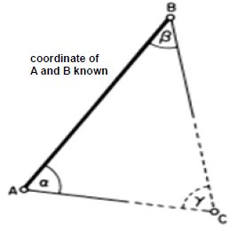
Figure 1: Intersection
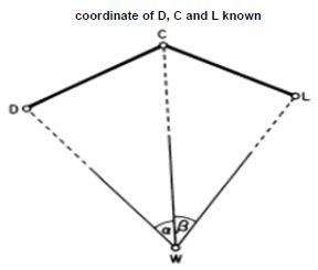
Figure 2: Resection
Solution Of Single-Point Adjustment On Clichés
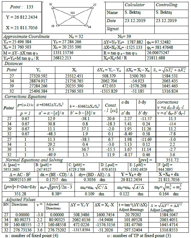
Let’s now see this single point adjustment step by step on a numerical application. In order to make single point adjustment on the clichés, first chart is arranged for all direction measurements. The procedures to be done to fill the chart and clichés are summarized below in Figure 3.
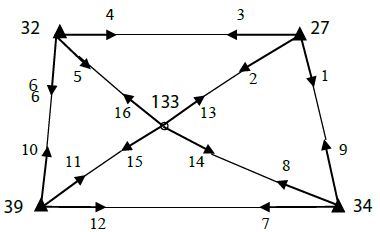
Figure 3: Numerical Example
In the triangulation network in the figure, fixed points 27, 32, 34, 39 are given with (Y, X) coordinates. The directions indicated by arrows were observed in the wax and given in the chart. Calculate the adjusted coordinates of the 133 point.
In example;
Number of measurements n=16 (number of observed directions)
Unknown number u=7 (2 coordinates + 5 orientation unknowns)
Redundancy measures f=n-u=9
– Firstly, the station point (SP), the point of target (TP), the observed directions (r) columns and the bearing angle (to) columns calculated from the coordinates are filled.
– Approximate coordinates (Yo, Xo) of the point to be estimated are required to calculate the bearing angles about the two point. For this purpose, the point to be estimated from the fixed points (Na: 32 and Nb: 39) two bearing angles.
ϕa=Zo.32 + r32-133=55.12320 + 42.40162=97.52482
ϕb=Zo.39 + r39-133=344.96144 + 36.51504=381.47648
The approximate coordinates of the point (133) to be estimated using the cliché are calculated in the cliché and written in the calculation section of the approximate coordinates in the cliché.
– Two different ways are followed to calculate the approximate value (Zo) of the oriented direction unknowns belonging to the station points. For the calculation of Zo at fixed points, only the arithmetic mean of the (to-r) differences calculated from the directions from the fixed point to the fixed point is taken. At the point to be estimated (adjusted), Zo is made by taking the arithmetic mean of the (to-r) differences to be calculated from all directions. Calculated Zo values are written in the column they belong to in the chart.
– The oriented direction column is calculated and filled as (α=r + Zo) for the directions to the points to be estimated from the fixed points and the direction observations made at the point to be estimated.
– The constant term (-∫) column is filled by computing (-∫=to – α) in units of [cc] for directed directions only.
Point adjustment on the cliché:
– Approximate coordinate calculation section of the cliché was filled in while preparing the chart.
– The point numbers and Y, X coordinates of all fixed points are written in the edge calculation section of the cliché. The coordinate differences and lengths of ∆Yo=Yi – Yo and ∆Xo=Xi – Xo from fixed points to the point to be estimated are calculated and written in the relevant columns.
– In the section of establishment of correction equations; First, the fixed point numbers are written in order up to the double-lined line, and for the values in the p (weight) column, they are filled as p=(u-1)/u . Here u: number of target point at fixed point. The weights here are not the weights of the directions, but the p coefficients come to reduce the orientation unknown at fixed points. The direction coefficients a and b are calculated in the form of
a=63662 ∆Yo/So2 b=-63662 ∆Xo/So2
in [cc/dm] unit by using the values in the edge calculation section of the cliché and written on the lines they belong to. After the double-lined line, the next section is filled. Again, the fixed point numbers and p weight values are written as 1 this time. The pre-filled and shifted values are written under the b columns in the form of
a’=a – [a]/n b’=b-[b]/n
– ∫ constant terms are taken from the chart and transferred to the cliché.
– In the section of establishment and solution of normal equations; Normal equation coefficients (A, B, C, D, E and F) are calculated from the values in p, a, a’, b, b’, -∫ columns in the upper part of the cliché and written in their places. Unknowns dx, dy are found and adjusted coordinates (Y, X) are calculated by adding them to approximate coordinates. In the upper part of the cliché, using dx, dy values, a.dx, b.dy, a’.dx, b’.dy columns are calculated. Go to the corrections section to the right of the vertical double-lined part of the cliché. In this section, corrections for the direction observations made from fixed points up to the double-lined are calculated from the equation v=a dx + b dy -∫, the corrections for the direction observations made from the point to be estimated point to the next section from the double-lined are from the equation v=a ‘dx + b’ dy -∫. are calculated and written in their places. The weighted sum of squares [pvv] of all corrections is calculated and replaced. As a control, the value of [pvv] is also calculated from the equation [pvv]=F + D dx + E dy. The average error of the unit measure mo, the average error of the coordinates mx, my, the point position error mp are calculated.
– Adjusted values section; The columns of point numbers viewed from the estimated point, observed direction and corrections are filled in (corrections were previously calculated). Corrections are added to the observed directions and adjusted directions are calculated so that the first gaze direction is zero. Using the adjusted coordinates of the point to be estimated, the adjusted bearing, adjusted lengths are calculated and written in the columns they belong to. In order to control the point adjustment made with cliché, the following control operations are carried out in the last calculated adjusted values section (Tables 1 and 2).
Table 1: Chart
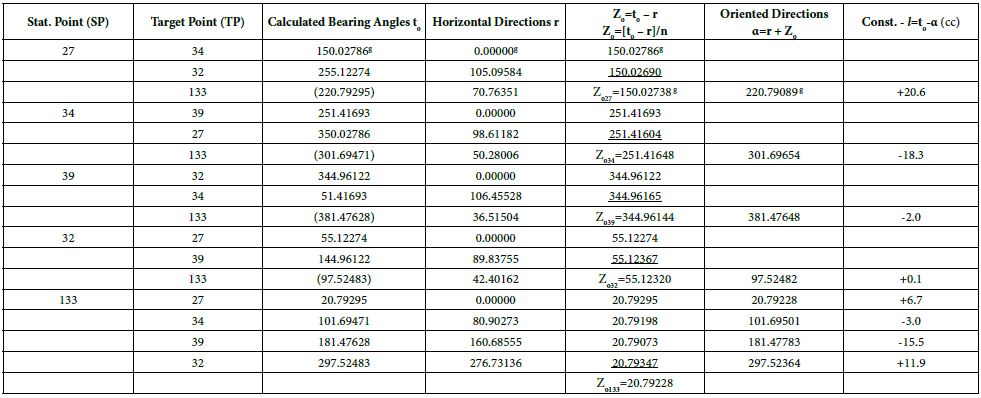
Table 2: Single Point Adjustments Cliché
Control Steps
- The two calculated values of [pvv] must be equal within the limit of rounding errors.
- The sum of corrections must be zero. This total should not be greater than 0.1cc due to rounding errors.
- The angles between adjusted directions and the angles between adjusted bearing should be equal. The difference between the angle values calculated in two different ways should not be greater than 0.1cc.
Warning: The value of estimated point’s coordinates (133) always is exactly correct. But the value of [pvv] is different from its actual value. Because corrections are not calculated for the direction observations made from fixed points in the cliché. Therefore, the calculated values of mo, my, mx, mp are not exactly correct. The actual values that should be are: [pvv]=489.48, mo=7.38 cc, mx=0.096 dm, my=0.107 dm and mp=0.144 dm.
Conclusion
When this problem is solved in the form of mixed resection without performing point adjustment, there are differences smaller than centimetre between the coordinates of the point 133 found by mixed resection and the coordinates found by adjustment. Although this difference is easily negligible for most practical needs, it is necessary to adjustment it in studies that require high precision.
In this study, we will show how the single point adjustment can be done according to the least squares (LSQ) theory on a cliché. Moreover, with today’s advanced calculation tools, all geodetic problems can be adjusted very quickly in accordance with the error theory by means of appropriate software.
References
- Allan A, Hollwey J, Maynes J (1968) Practical Field Surveying and Computations, American Elsevier Publishing Co, Inc, New York.
- Anderson J, Mikhail E (1998) Surveying: Theory and Practice, 7th edition, WCB/McGraw-Hill, New York.
- Bannister A, Raymond S, Baker R (1984) Surveying, 6th edition, Longman Scientific & Technical, Essex, England.
- Bektas S (1992) “3D triangulation network” Turkey III. Map of technicians and Services Conference “13-16 April 1992 in Ankara.
- Bektaş S (1997) Space Resection, Map and Cadastre Engineering Journal, issue: 83, p.72-79, October 1997, Ankara.
- Bektaş S (2016) Practical Geodesy II. Edition, OMU publications, Samsun.
- Öztürk,E – Serbetçi M (1989) “Adjustment Calculation Volume II”, KTÜ publications, publication number: 144, page: 310, Trabzon.
- Uren J, Price WF (1985) Intersection and Resection. In: Surveying for Engineers. English Language Book Society student editions. Palgrave, London.