Abstract
This project is therefore aimed at designing and construction of a pure sine wave inverter system of 7.5 kVA analyzed in performance and can be used to convert electrochemical energy into an alternating current (AC) supply. The major tests that were carried out all met the expected specifications with negligible deviation or tolerance. One thing was peculiar about the results; each of the tests that were carried out in each of the subsystems that make up the inverter system was done in relation to the next subsystem that was connected to it. The outputs from the inverter system were all as expected as shown by the final results. When the final installation was made, the system was tested by gradually loading it to see that it responds to the load increase as expected; and after the load test we observed that batteries voltage dropped slightly due to the loading effect and that was normal. Based on the pattern of tests and observations used in this project, it is expected that the system performs its intended duty throughout its useful life as long as it is used as prescribed.
Keywords
Battery, Energy, Load, Performance, Power
Introduction
Electrical energy or electrical power can be generated from primary energy sources which include geothermal power, mechanical power, solar power, kinetic energy of flowing water and wind, etc. this was discovered by Michael Faraday, a British scientist in the 1820s and 1830s. According to the law of conservation of energy also known as the law of science which states that energy can neither be created nor destroyed but can be transformed from one form to another. Series of researches have been carried out to fascinate the development on the technology on energy generation from different primary sources [1]. Despite all these technologies, due to the fact that everyone needs electrical energy as a result of high population and the slow rate of technological development in the country, the amount of energy distributed becomes insufficient for people and the need keeps pressing to generate an alternative supply from primary sources of energy such as hydro, wind, solar and chemical energy. In order to generate electrical power from direct current (DC) to Alternating current (AC), a device called Inverter is employed. While a rectifier circuit is used on the other hand to convert electricity from Alternating current (AC) back to Direct current (DC) [2]. This project is therefore aimed at designing and construction of a pure sine wave inverter system of 7.5 kVA analysed in performance and can be used to convert electrochemical energy into an alternating current (AC) supply. According to the Authoritative Dictionary of IEEE Standards Terms (IEEE, 2000), inverter is an electrical power converter that changes direct current (DC) to alternating current (AC). The converted AC can be at any required voltage and frequency with the use of appropriate transformers, switching, and control circuits. The inverter performs the opposite function of a rectifier [3]. The electrical inverter is a high-power electronic oscillator. It is so named because early mechanical AC to DC converters was made to work in reverse, and thus was “inverted”, to convert DC to AC. Inverters do not suffer much from all these except that the batteries are consumed very fast as the load increases calling for constant recharging of the batteries after each use [4].
Literature Review
Osuwa and Peter, 2014, gave the brief idea about the production of solid state inverters which provides environmentally friendly alternative for uninterruptible power supply for the working of different gadgets and for sustainable economy. This study is thus anchor on the making of 1 kVA inverter for provision of power using locally sourced 80 Ah 12 volts deep cycle battery, oscillator determined MOSFETs and a transformer along with other electronic components [5]. In build an inverter for the conversion of DC to AC at a normal frequency of 50 Hz, due consideration is given to the switching speed of the oscillator used to make sure that the MOSFETs in their two channels operate in their saturation and cut off states when appropriately driven by oscillator outputs in a way to complement each other.
Omitola et.al, 2014 discuss that researchers proposed that in the modern society, electricity has great control over the most daily activities for instance in domestic and industrial utilization of electric power for operations. Electricity can be generated from public supply to users in different ways including the use of water, wind or steam energy to drive the turbine as well as more recently the use of gas generators, astral energy and nuclear energy are as well sources of electricity [6,7].
An inverter is an electronic device that converts electrical power from DC form to AC form. Its typical application is to convert battery voltage (stored D.C voltage) into a normal house A.C voltage to power electrical devices such as TV, fridge etc. when an A.C power from the national grid is not available (wikipedia).
Chan and Bowler, 1974, reveals the more up-to date types of inverters are two or more transformer coupled inverters, which might be either connected in series and/or in parallel, to bring desirable result, but the only issue is the reduced time duration because of its high power consumption when working at full capacity. (Gottles, 1985). The other drawback of the above named inverters are reduced efficiency absence of dc power energy restoration (that is, chargers were not included for charging back-up batteries in the presence of public power supply). Also there is no capacity to switch from dc source to ac source when power is restored. Although, the latest products of solar energy to electrical energy converters include battery charging circuits but does not have the capacity to switching to public power supply (PPS).
Methodology
System Operation
The batteries are the back-up source for power generation conversion of chemical energy into electricity. The power produced by the battery bank was then transferred to the inverter unit. The battery monitors in the inverter monitors the rate at which electric current were drawn in and out of the battery. It turns off charge when the battery reaches the optimum charging point and turns it on when it goes below a certain level. It fully charges the battery without permitting overcharge. The batteries are the key component in this power system. It provided energy storage for the system. The energy stored in the batteries was then used to power the load but it was first converted to AC voltage by the use of an inverter due to they were AC loads. The photovoltaic ally produced direct current was commuted periodically by controlled oscillatory system and feed to power electronic semiconductor switches such as JFET which were connected the power transformer. Here the voltage was stepped up to the desired ac voltage. The inverter could also charge the battery when there is public power supply (Figure 1).
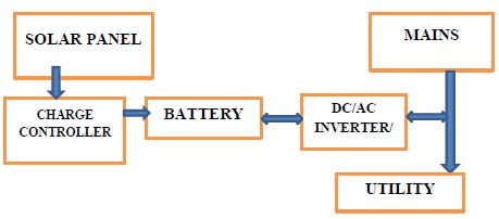
Figure 1: Block diagram of operational principle of a solar inverter system.
Battery Bank
A battery bank is a group of batteries connected together using series or parallel wiring. This allows more power to be stored than using a single battery. A battery bank is the result of joining two or more batteries together for a single application. What does this accomplish? Well, by connecting batteries, you can increase the voltage, amperage, or both. When you need more power, instead of getting yourself a massive super tanker of an RV battery for example, you can construct a battery bank. A battery bank is a group of batteries connected together using series or parallel wiring. This allows more power to be stored than using a single battery. A battery bank allows you to store electricity generated by solar PV system for use at any time. (Solarmango.com)
Battery Connection Scheme
The first thing you need to know is that there are two primary ways to successfully connect two or more batteries: The first is via a series and the second is called parallel [8].
Series Connection. A series connection adds the voltage of the two batteries, but it keeps the same amperage rating (also known as Amp Hours). For example, these two 6-volt batteries joined in series now produce 12 volts, but they still have a total capacity of 10 amps. To connect batteries in a series, use jumper wire to connect the negative terminal of the first battery to the positive terminal of the second battery. Use another set of cables to connect the open positive and negative terminals to your application. Never cross the remaining open positive and open negative terminals with each other, as this will short circuit the batteries and cause damage or injury (Figure 2).
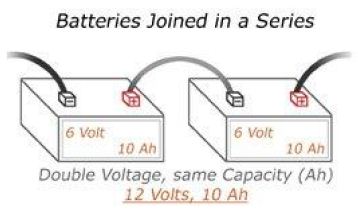
Figure 2: Battery connection in series.
Be sure the batteries you’re connecting have the same voltage and capacity rating. Otherwise, you may end up with charging problems, and shortened battery life.
Parallel Connections. The other type of connection is parallel. Parallel connections will increase the current rating, but the voltage will stay the same. In the Parallel diagram, we’re back to 6 volts, but the amps increase to 20 AH. It’s important to note that because the amperage of the batteries increased, you may need a heavier-duty cable to keep the cables from burning out. To join batteries in parallel, use a jumper wire to connect both the positive terminals, and another jumper wire to connect both the negative terminals of both batteries to each other. Negative to negative and positive to positive. You can connect your load to one of the batteries, and it will drain both equally. However, the preferred method for keeping the batteries equalized is to connect to the positive at one end of the battery pack, and the negative at the other end of the pack. It is also possible to connect batteries in what is called a series/parallel configuration, but it may sound confusing, but this is the way you can increase your voltage output and Amp/Hour rating. To do this successfully, you need at least 4 batteries (Figure 3).
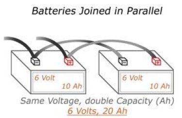
Figure 3: Battery connection in parallel.
This is a combination of the above methods and is used for 2 V, 6 V or 12 V batteries to achieve both a higher system voltage and capacity. For example; 4 × 6 V 150 Ah batteries wired in series/parallel will give you 12 V at 300 Ah. 4 × 12 V 150 Ah batteries can be wired in series/parallel to give you 24 V with 300 Ah capacity (Figure 4) [9-36].
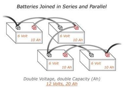
Figure 4: Battery connection of series and parallel.
Results
This chapter presents the test results of the works that were carried out in this project. At the end of the installation, the system was tested to ensure that it meets the desired stated objectives and specifications that guided the entire project work. The results of the test carried out are as below;
Test Carried Out
1. Physical examination
2. Is it fully charged?
3. How much charge is left in it?
4. Does it meet the manufacturer specification?
5. Device testing
6. Continuity test
7. Short circuit test
Device Testing
To test the Inverter, a load of up to 6000 VA was connected to the device to test if the device can carry up to the power stipulated for it to bear.
Continuity Test
The continuity test is carried out to avoid any form of an open circuit. The presence of an open circuit in any electrical system will create an open circuit fault in the system and the system will not function. The wires have to be continuous all the way from one terminal to another. The lead used in the soldering of the components must be well soldered and there should be no any form of partial contact as this might initiate an open circuit in the system.
Short Circuit Test
A short circuit occurs when the live and the neutral wires touch each other. When this happens, the current goes infinitely high and can blow up the entire system [6]. There should be no form of short circuit, be it on the legs of the integrated circuits or along the wires. Short circuit fault is a very costly fault as it can blow up the whole system and should be avoided as much as possible, so this test is very important prior to the powering of the inverter system. To determine the system failure rate, the part count analysis of the various components is required.
Performance Evaluation Test on the Inverter Battery
The inverter battery was subjected to two types of test;
1. No load test; and
2. Load test.
No Load Performance Test
A no-loads test was done on the inverter initially after completion, the output of the inverter was measured using a voltmeter (Table 1).
Table 1: No-Load Test on the Inverter.
|
Description |
Values |
|
Input Voltage |
120 V |
|
Output Voltage |
230 V |
|
Current from Battery |
220 A |
| Frequency |
50 HZ |
Calculation of the Real Power for the Inverter:
P(kw)=P(kva) × P.F
Where P.F=0.8;
P(kw)=7500 × 0.8
P(kw)=6000 w
Formula calculation, to obtain the maximum current to be demanded by the inverter from the battery; Power (P); P=IV
I=p/v
When; P=6000 w, V=120 v
I=7500/120
I=50 A
Calculation for the battery scheme:
- Using analytical approach;
- Terminal battery voltage before charge:
Using a series method,
Having 10 batteries rated:
12.5+12.4+12.4+12.4+12.5+12.5+12.4+12.5+12.4+12.5=124.5 v.
In a battery, there are 6 cells,
Per cell we have 2 v, 2 × 6=12 v
Maximum for a cell is 2.2 v, 2.2 × 6=13.2 v.
Transient/tolerance value=±13.4.
Terminal battery voltage after charge:
Using a series method,
Having 10 batteries rated:
12.7+12.6+12.8+12.7+12.7+12.7+12.7+12.6+12.8+12.7=126.4 v
Calculation for battery running hour:
Analytical approach:
T(hr)=volt × AH × E/load
where E is power efficiency AH is ampere per hour of the battery capacity
a. when load L=1000 w, V=120 v, battery capacity=220 AH
T(hr)=120 × 220 × 0.9/1000=23.76 hours
b. when load L=2000 w, V=120 v, AH=220 A
T(hr)=120 × 220 × 0.9/2000=11.88 hours
c. when load L=3000 w, V=120 v, AH=220 A
T(hr)=120 × 220 × 0.9/3000=7.92 hours
d. when load L=4000 w, V=120 v, AH=220 A
T(hr)=120 × 220 × 0.9/4000=5.94 hours
e. when load L=5000 w, V=120 v, AH=220 A
T(hr)=120 × 220 × 0.9/5000=4.75 hours (Table 2).
Table 2: Calculation for battery running hour Analytical approach.
|
Load (w) |
Time (H) (Approximated value) |
|
1000 |
24 |
|
2000 |
12 |
| 3000 |
8 |
| 4000 |
6 |
|
5000 |
5 |
Load Performance Test
The constructed inverter was subjected to different kinds of loads to determine the efficiency, how long the inverter systems can power the loads.
In carrying out the load test, the following loads were used:
- A megger tester
- Multi-meter
- Load
- Clamp-meter.
The test results and performance tests are shown in the sub-sections below:
- Inductive load performance is shown in Table 3 and Figure 5.
- Resistive load performance is shown in Figures 6, 7 and Tables 4-6.
Table 3: Inductive loads test for the inverter.
|
S/N |
Load (W) | Time (1 hour interval) | Battery discharge rate (V) |
|
1 |
450 | 11:30 am | 122.6 |
|
2 |
450 | 12:30 pm |
122.4 |
| 3 | 450 | 1:30 pm |
122.4 |
| 4 | 450 | 2:30 pm |
122.3 |
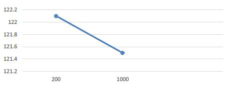
Figure 5: Load Performance Analysis of Inductive Load.
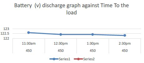
Figure 6: Graphical representation of load performance analysis of resistive calculation of Load.
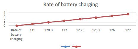
Figure 7: Graphical representation of the Inverter battery charging with respect to time.
Table 4: Inductive loads test for the inverter.
|
S/N |
Item | P (w) | Duration (30 Mins Interval) | ||
|
DC (V) input |
AC (V) output |
I (A) output |
|||
|
1 |
Electric bulb | 200 | 122.1 | 230 |
2.2 |
| 2 | Electric Iron | 1000 | 121.5 | 229 |
6.9 |
Table 5: Load Description.
|
Item |
Description |
Quantity | Rating (W) |
|
1 |
Television | 1 | 62 |
| 2 | Monitor | 1 |
193 |
|
3 |
Fan | 3 | 450 |
| 4 | Bulb | 1 |
200 |
| 5 | Air condition | 1 |
750 |
|
6 |
Iron | 1 | 1000 |
| Total= |
2655 |
Table 6: Load Performance Analysis.
|
Time |
Load (W) | Current (I) | Battery (V) | Output voltage (V) | Output current (I) |
Load (%) |
|
11.00 |
TV (63)
Monitor (193) |
0.1 | 123.4 | 240 | 0.5 |
3 |
|
12.00 |
Fan (150) | 1.9 | 123.3 | 236 | 1.1 |
5 |
|
1.00 |
Fan (150) | 2.4 | 122.3 | 233 | 1.7 |
8 |
|
2.00 |
Bulb (200) | 2.6 | 122.1 | 230 | 2.2 |
9 |
|
3.00 |
A.C (750) | 3.6 | 121.8 | 230 | 2.9 |
12 |
|
4.00 |
Electric Iron (1000) | 6.7 | 121.5 | 229 | 6.9
15.3 |
16 |
The inverter was subject to two kinds of loads to determine the efficiency, how long the inverter systems can power the loads.
- The resistive loads which are; energy saving bulbs and soldering iron.
- The inductive load which are; electric fans and Air Conditions.
The tests carried out on the inverter and the readings taken with the use of multi-meter are as follows:
Discussion
The results of the tests that were carried out throughout the whole determination were all gotten through systematic checks and observations, and using the appropriate test tools and equipment where necessary. The major tests that were carried out all met the expected specifications with negligible deviation or tolerance. One thing was peculiar about the results; each of the tests that were carried out in each of the subsystems that make up the inverter system was done in relation to the next subsystem that was connected to it.
The outputs from the inverter system were all as expected as shown by the final results. When the final installation was made, the system was tested by gradually loading it to see that it responds to the load increase as expected; and after the load test we observed that batteries voltage dropped slightly due to the loading effect and that was normal.
Before final installation, the different sections that make the whole system were tested individually. This pattern was adopted to make troubleshooting, analysis and testing easy and reliable. It is expected that all the results of the tests that were carried out continuously conform to the specified standards as long as the system is used within its capacity and under the standard test conditions. Based on the pattern of tests and observations used in this project, it is expected that the system performs its intended duty throughout its useful life as long as it is used as prescribed, and this is because of the fact that the system was designed under standard operating conditions of the immediate environment.
Conclusion
The application of our knowledge of engineering in solving our local problem is one thing desperately needed in our country today. That is the opportunity this project offered us; by the implementation of this project, we have successfully made the laboratory less reliant on grid supplied energy which would boost productivity. After the implementation of the 7.5 kVA inverter installed for the department, the following were achieved:
- We successfully did a proper load sizing of the department.
- We successfully learnt and practiced the load on inverters in buildings.
- We successfully determined the battery bank capacity of the 7.5 kVA pure sine wave inverter we installed in the department.
- We as well gained great entrepreneurial skill through this project. This is of immense benefit as it would reduce our dependence on the job market for survival after school.
- The end product of the project is the availability of a reliable and consistent power supply for the department.
Recommendations
- A maintenance check (e.g. periodic maintenance) should be carried out on the photovoltaic components (the solar panels, the power inverter, the charge controller, the batteries, the wires and cables, the monitors and meters) probably once a month. This will ensure that any fault is discovered and looked into on time. The components should not be tampered with in case any fault is discovered, experienced technicians should be contacted to check on the problem and proffer solutions.
- We would recommend that close attention be paid to the loading of the inverter. For the best interest of the life span of the inverter, it should not be run at the peak load. Members of staff should ensure that heavy duty loads are not connected to the inverter during the usage of the inverter.
- We recommend that students be issued their projects early enough to enable them learn in details what the project entails and projects like this (solar energy based) should be encouraged by the government to ensure optimal solutions to major issues like power failure problems.
References
- Abatan OA, Adewale AO, Alabi AA (2013) Constant Electricity Generation From Self-Charging Inverter. International Journal of Emerging Technology and Advanced Engineering 3: 694-698.
- Assad Abu-Jasser, (2010) A stand-alone photovoltaic System, Case Study: A Residence in Gaza. Journal of Applied Science in Environment Sanitation 5: 81-91.
- Adeoye SA and Akanni OS (2017) Development of 0.75 kVA Modified Sine Wave Inverter for a viewing Centre in Nigeria. International Journal of Advance Research and Innovation 5: 333-337.
- Baliunas, Sallie L, Willie Soon (2001) Washington Roundtable on Science and public Policy: Climate history and the sun.
- Balou (2009) what types of driver circuits are there?
- Battery Bank (2019) http://www.solarmango.com/dictionary/bank
- Bellis Mary (2019) History and Timeline of the Battery.
- Bird BM, Kings KG (1993) an introduction to power electronics.
- Chan T, Bowler P (1974) International Conference on Power Electronics, Power Semiconductors and their Applications 7-9: 237-251.
- Connexion France. 4 April (2017) Delayed at the station? Get pedalling to charge your phone”.
- Dave Etchells “The Great Battery Shootout”.
- Prince DC (1925) The Inverter. GE Review 28: 676-81.
- Electrical4u (2015) Online Electrical Engineering Study Site. Transformers types and principles 25.
- Emerson Network Power: Effects of AC Ripple Current on VRLA Battery Life” by https://enacademic.com/dic.nsf/enwiki/1355813
- Geoffrey Poulton (2007) Princeton information technology. http://www.researchgate.net
- IEEE Standards Terms (2000) The Authoritative Dictionary of IEEE Standards Terms (2000) Seventh Edition, IEEE Press, ISBN0-7381-2601-2: 588
- Osuwa JC, Peter CF (2014) Construction and implementation of 1kva Inverter. IOSR Journal of Applied Physics (IOSR-JAP) 6: 56-58.
- Mansoori Ali G, Enayati Nader, Agyarko L Barnie (2015) Energy: Sources, Utilization, Legislation, Sustainability, Illinois as Model State. World Scientific.
- Battery Charging (2018) (Pdf): LM2576,LM3420,LP2951,LP2952. ti.com
- Martin RG, (2002) Electronic Design from Concept to Reality, Discovery Press, India: 45-65.
- Martin LaMonica (2011) Motion-powered gadget charger back on track. CNET
- (2001) AN913: Switch-Mode, Linear, and Pulse Charging Techniques for Li+ Battery in Mobile Phones and PDAs.
- MIT Electric Team Vehicle December (2008) A Guide to Understanding Battery Specifications “mit.edu.
- Ned Mohan and William P Robinson (1989) design and Development of inverter with AVR using switch. journal.au.edu
- Olusegun O, Omitola Segun O, Olatinwo, Taiwo R. Oyedare (2001) Design and Construction of 1KW (1000VA).
- Omitola JK (2014) Design and construction of1KW (1000VA) PowerInverter. Journal of Innovative Systems Designand Engineering 2-12.
- Phil Weicker (2013) A Systems Approach to Lithium-Ion Battery Management. Artech House
- Pulse Maintenance charging:” Archived March 9, 2012, at the Wayback Machine.
- Recharger definition and meaning – Collins English Dictionary” (“Recharge – definition of recharge in English – Oxford Dictionaries”. Retrieved 26 June, 2019.
- Kayne R (2013) What is a Power Inverter.
- Sheu Akeem Lawal, Alade Olusope Michael: Design, Construction And Performance Evaluation Of 1kva Pure Sine Wave Power Inverter, International Journal of Scientific & Engineering Research
- Shuler CA (1984) Electronic Principle and Application. Glencoel McGraw Hill Columbus.
- Tepco Egypt (2010) Types of Loads.
- Theraja BL (2005) A Textbook of Electrical technology (22nd Edition) S Chand and company Ltd India Pg 2167-2176.
- William DS, (2001) Operation amplifier with linear integration circuit, Christopher R couty of charles E Merrill pulishing co, Chicago pp: 217-241.
- Windy Dankoff, (2001) How to Choose an Inverter for an Independent Energy System, Home Power 74-78.