Abstract
In this overview work the changes in the structure and properties of commercially pure niobium and tantalum under conditions of hard cyclic viscoplastic deformation are studied. During linear compression-tension deformation of the sample, wich was carried out in the strain control mode in the range from ε=±0.2% to ε=±3.0% with a frequency f=0.2-2.5 Hz and with a number of cycles in the range from 20 up to 40, respectively. In addition to classical methods of severe plastic deformation, this method can be used to improve and stabilize the microstructure, mechanical, physical and functional properties of single crystalline, coarse-grained, ultrafine and nanocrystalline metallic materials. The experimental results obtained can be used to study the stability and viability of metallic materials, as well as predict their suitability over time in harsh environments such as space and military applications, and thereby expand new understandings and connections in materials science.
Impact Statement
This overview article comprehensively reviews recent advantages of the development of niobium and tantalum structure and properties studyied by severe plastic deformation (SPD) and hard cyclic viscoplastic deformation (HCVD) at room temperature.
Keywords
Severe plastic deformation, Hard cyclic viscoplastic deformation, Microstructure, Mechanical properties, Physical properties, Wear, Tribological properties, Viability, Electrical conductivity, Hydrogen storage, Young´s modulus
Introduction
Written science in the field of SPD first appeared in the late 20th century [1,2], but archaeological research has shown that the process was known and used at least 2,700 years ago [3] in the production of knives and swords. Humanity has been working with metals since the Bronze Age and has created a common and understandable terminology for all communities. For example, the metalworking process with severe plastic deformation (SPD) in turn contains about a hundred technological processes and a large number of terms to describe these processes and their results. The field of SPD is constantly being improved with new methods already developed and partially patented for more than a hundred names. Currently, more than 1000 papers are published annually in the field of SPD. The emergence and application of new processes in materials science also require the development and addition of new terminologies.It is well known, that the SPD methods are popular due to their ability to modify the microstructure [4-6] and mechanical properties [7-10] of various plastic metal materials. At that time, it was well known that the mechanical properties of SPD-processed materials were significantly better compared to their coarse-grained counterparts [11-15]. Experimental results show that it is possible to change the initial microstructure from a coarse-grained (CG) to an ultrafine-grained (UFG) structure with grain sizes in the range from 1000 to 100 nanometers at ECAP and to a nanocrystalline (NC) structure with a crystal size below 100 nanometers [16-21] at HPT. Unfortunately, the scientific works on SPD listed in [1-21] have so far mainly studied only changes in the microstructure and mechanical properties of materials, such as hardness and strength. At the same time, a number of recent scientific articles have shown that changes in microstructure and mechanical properties during SPD also lead to changes in electrical conductivity [22-27], phase transformations [28-31], wear resistance [32-35], cyclic plasticity [36-41], and so on. Unfortunately, in these works relatively little attention was paid to changes in functional properties, which limits the widespread use of these materials in modern industry.
Components and entire systems are characterized by time-varying cyclic loads and often random load sequences that can cause material fatigue and damage. Therefore, understanding the relationship between fatigue damage and random cyclic loading is a necessary prerequisite for reliable sizing of components and structures. However, this design of fatigue components is motivated not only by the desire to avoid damage to products and their repair. Today, issues of materials and energy efficiency are becoming increasingly important, and therefore increasing their sustainability during operation, which requires accurate knowledge of the operating loads of the systems and the corresponding fatigue behavior of the materials. Sustainability in today’s sense means making the most efficient use of available resources, and this goal can only be achieved for many components and structures if the load sequences present in the operation are known and taken into account when optimizing materials, design and production in industry. Information on the latest developments in the field of variable load fatigue, new scientific approaches and industrial applications of materials, components and designs is up to date. The achievements and results of research in recent years, new approaches and the latest processes in various industries are highly appreciated.
Tension-compression amplitudes, as characteristic features of typical workload sequences in various mechanisms, are becoming very important parameters in the design and optimization of components and structures. Material testing methods such as low cycle fatigue (LCF) [42] and high cycle fatigue (HCF) [43], ratchet [44], Bauschinger effect [45-47], Young’s modulus [54], are very important to determine the durability of materials in actual use.
For example, the number of cycles to failure for the LCF test method is typically less than 10,000, and the failure mode is typically ductile failure. During HCF testing, the material or component fails after a large number of cycles, typically greater than 10,000. Thus, HCF is typically associated with very low strain amplitude at tensile, elastic deformation, crack initiation and growth. The difference between these test methods, LCF and HCF, depends on the level of strain under tensile stresses, the ductility of the material and the degree of elastic deformation. Fatigue behavior is characterized by loading frequency, loading history, loading type, ambient temperature, microstructure, defects and residual stresses in the material.
The ratcheting method uses only tensile deformation with controlled tensile strain and a very small number of cycles. The ratcheting method is based on the well-known Bauschinger effect. The method for testing of metallic materials in viscoplastic states is so called as Hard Cylic Viscoplastic Deformation (HCVD) is described in [55-59]. The viscoplastic behavior and hardening/softening of metallic materials allows you to very quickly, simply and cheaply change and study the structure and properties of metallic materials. For example, this method has been used at firstly to study the microstructure, mechanical and functional properties of metallic materials such as coarse grained (CG) copper [60], ultrafine-grained copper alloys [61], pure niobium [62-65], pure tantalum [66-69] with oligocrystalline structure and also Ni-based single-crystal superalloy [70-73], etc.
This overview study on Nb and Ta by uising HCVD technique is based primarily on my own research work in which I have studied materials using various SPD techniques. HCVD principles were first presented in 2004 at the TMS Ultrafine Grained Materials III Annual Meeting, Charlotte, North Carolina, USA [74] and at the 4th DAAAM International Conference on Industrial Engineering – Innovation as a Competitive Advantage for SMEs, Tallinn, Estonia. [75]. Unfortunately, HCVD as a new process in materials science has not yet been widely used in studying the evolution of the structure and properties of metallic materials. At present time the stability and viability of metallic materials, and predicting their suitability over time in harsh environments such as space and military applications is actual. Studying the behavior of metallic materials in viscoplastic states using HCVD method allows us to expand concepts and new connections in materials science.
Experimental Section
Materials
The materials for present experimental work were technically pure niobium (Nb) and tantalum (Ta) ingots, which were produced by electron beam melting (EBM) technique on Neo Performance Materials (NPM) Silmet AS, Estonia. The chemical analysis of NPM Silmet AS showed that the pure Nb ingots, with diameter of 220 mm, contained the following non-metallic elements: N (30 ppm), O (72 ppm), H (˂10 ppm), c (˂20 ppm), and metallic elements: Ta (160 ppm), Si (˂20 ppm), P (˂15 ppm), Mo (˂10 ppm), and W+Mo (˂20 ppm), respectively.
The Ta inots diameter was 120 mm and an oligocrystalline macrostructure. The chemical composition of Ta was: Al, Mg, Pb, Cu, Fe, Mo, Mn, Na, Sn (for all ˂5 ppm), Nb (˂20 ppm), W (˂10 ppm), and Si (˂10 ppm) and non-metallic elements: N (˂ 20 ppm), O (˂ 30 ppm), H (˂10 ppm), S (˂10 ppm), C (˂10 ppm), respectively. These ingots had a oligocrystalline macrostructure up to 15-20 cm in length and approximately 5-6 cm in thickness (Figure 1). The Nb and Ta samples were before for recrystallization heat treated in vacuum furnace at 1100°C for 30 min.
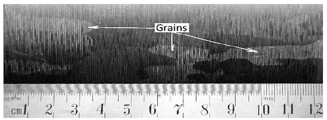
Figure 1: Oligocrystalline macrostructure of Ta after EBM by industrial processing
The IEAP Technique and Test Samples Manufacturing
Using hard-to-deform Nb and Ta samples, the ECAP matrix was modified and a new so-called “indirect extrusion angle pressing” (IEAP) method was developed [34,63,66,67,76]. IEAP format channels do not have the same cross-section. The cross-section of the output channel, taking into account the elastic deformation of the base metal, was reduced to 5-7%, which makes it possible to use the conveyor method when pressing without intermediate processing of the cross-section of the workpiece. This is due to elastic deformation of the matrix and an increase in the cross-section of the sample during pressing. To process workpieces under HCVD, the developed IEAP technology was used. In the work under consideration, the microstructure of the samples under study was modified up to 12 passes of the IEAP along the BC route. The maximum degree of von Mises deformation during one pressing was 1.155, and after 12 passes – up to ~13.86, respectively. As experiments have shown, this IEAP die is convenient for processing high-strength materials, since at higher extrusion passes, when the strength of the materials increases sharply, the friction between the punch and the matrix during pressing also increases, and thus the risk of damage to the matrix or plunger increases. [67]. For comparison, the same metals (Ta and Nb of the oligocrystalline as well as recrystallization structure received at heat treatment) were used so that the results could be compared. Using the IEAP method, samples with dimensions of 12x12x130 mm are produced. The processing steps of IEAP samples are shown in Figure 2.
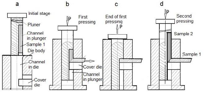
Figure 2: Diagram of the IEAP stamp and the corresponding stages (a, b, c, d) of sample processing using the so-called conveyor method, with this method in the stamp at the final stage two samples are simultaneously processed, the second sample pushes out the first (d).
The specimens for hard cyclic viscoplastic deformation (HCVD) were manufacturing from EBM and IEAP-treated samples (Figure 3a and 3b). The mechanical cutting and electroerosion tchniques were used. The samples for electrical conduction, hardness, gases content, density, XRD, and microstructure study were cut off from HCVD sample (Figure 3c) and tensile tests minisamples Figure 3f) were cut off by electrical discharge method from HCVD sample (Figure 3d and 3e). The strain amplitude at HCVD testing was measured by extensometer with base length of 10 mm and it was mounted on sample with minimal cross section (Figure 3c). The strain amplitude for other cross sections were calculated. IEAP of the samples was carried out on a hydraulic press with a capacity of 100 tons [68].
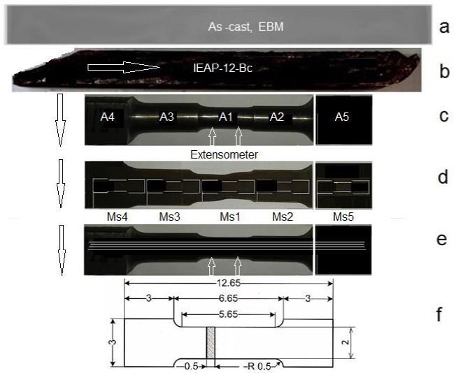
Figure 3: Mechanically cut sample from EBM ingot and heat treated at 1100°C for 30 minutes (a), IEAP treated sample (b), test sample for Young’s modulus measure by HCVD with stepped cross section (specimens A1, A2, A3, A4, A5 and A6 (as cast) with 5 mm in length) for measuring microhardness, density, XRD, gases content and electrical conductivity (c), mini-specimens (d) for tensile strength tests (MS1, MS2, MS3, MS4, MS5 and MS6-as cast), cut from the sample after HCVD in diametrical section in three layers 1, 2 and 3 (e), cut out using the electrical discharge method, and a mini-specimen for tensile testing with dimensions in mm is shown in (e).
The HCVD Technique
The HCVD technique was elaborated for materials structure modifing and properties testing [53,58,74,75]. The HCVD as a new process is not yet widespread in the study of metallic materials structure and properties evolution. It is well known that “viscoplasticity” is a response of solids involving time-dependent and irreversible deformations. In this research, we investigate the viscoplasticity of metallic materials and the accompanying changes in microstructure and properties at room temperature. To do this, we use cyclic deformation with a constant strain amplitude at each stage of the experiment. In the HCVD process, the strain amplitude ranges from ε=±0.2% to ±3.0% per cycle. The HCVD was conducted on an Instron-8516 metrials tester, Germany.This method is characterized by the generation of cyclic stress, the magnitude of which depends on the strength properties of the material at a given compression-tension deformation or strain amplitude. Therefore, this research method of metallic materials is called hard cyclic viscoplastic deformation (HCVD). The name of this new process begins with the word “hard”, which means that tensile and compressive deformations are used in the high-amplitude viscoplastic field in both tension and compression. The evolution of the microstructure of mixed metal materials is mainly studied from the deformation rate, the number of cycles, and the deformation stress amplitude of the HCVD method. The effect of HCVD on the improvement of the mechanical and physical properties of test materials has been described in various works [61,69,70,73]. In present overview work these large strain amplitudes of ε1=±0.2%, ε2 ±0.5%, ε3 ±1.0%, ε4 ±1.5%, ε5 ±2.0%, ε6 ±2.5%, and ε7±3.0% are used, respectively. At each degree of deformation, up to 20÷30 cycles are performed. The cycles number depend on material mechanical properties and viability. The frequency of cycling was chosed in the interval of ƒ=0.5 to 2.5 Hz, and were ƒ1=0.5 Hz, ƒ2=1.0 Hz, ƒ3=1.5 Hz, ƒ4=2.0 Hz, and ƒ5=2.5 Hz, respectively. The number of tests of the HCVD method starts from 20 cycles and up to 30 cycles per test for a series with the corresponding constant strain amplitude. The maximal number of cycles was not more then 100 for one sample. The frequency and strain amplitude at HCVD influenced on the strain rate and corresponding changes in the microstructure and properties.
To achieve the required results, the rated voltage, frequency, and a number of cycles are selected based on the test results. Usually, the technical strength is the strength of various constructions in calculations in elastic strain up to ε1=0.2% at tensile deformation, that is, until the beginning of plastic deformation of the material. In the LCF and HCF tests, the amount of elastic deformation is small, less than 0.2% of the deformation. At such a value of deformation, the metal material has an elastic behavior. The HCVD method determines the magnitude of the controlled amplitude of deformation and is controlled by an extensometer using a computer program that controls the process and displays the corresponding results on the computer screen. Typically, the fatigue test of metallic materials checks the tensile strength but does not check the deformation, which develops automatically according to the mechanical properties of the material. Micromechanical multiscale viscoplastic theory has been developed to relate the microscale mechanical responses of amorphous and crystalline subphases to the macroscale mechanical behavior of fibers, including cyclic hardening and stress recovery responses. The HCVD method can be used as a new test method in materials science when it is necessary to determine the behavior of a material under stresses that can exceed the elastic limit and deform under extreme operating conditions. For example, such extremes may occur in aviation, space, or military technology because these devices have a minimum calculated strength or margin of safety compared to other devices. For example, the compressor blades of a turbojet engine for military fighters have a safety margin of no more than 3-5%.
Methods for Other Properties Testing
The microhardness in cross section of samples A1, A2, A3, A4, A5, and A6 was measured using a Mikromet-2001 tester after holding for 12 s at a load of 50 and 100 g. At follows, the mini-samples (MS1, MS2, MS3, MS4, MS5 and MS6-as cast) at tension up to fracture were tested on the MDD MK2 Stand test system manufactured in the UK. The tribological behavior of materials under dry sliding conditions was investigated before and after IEAP, HCVD and heat treatment to provide a comparison over a range of material properties as well as collected strain to understand their influence on the coefficient of friction and on the specific wear rate. Dry sliding wear was studied in a ball-plate system with a tribometer (CETR, Bruker, and UMT2) using an aluminum oxide (Al2O3) ball with a diameter of 3 mm as a counter surface. The coefficient of friction (COF) was obtained automatically. For wear volume calculations, the cross-sectional area of the worn tracks was measured by the Mahr Pertohometer PGK 120 Concept 7.21. The content of metals inclusions (in ppm) were studied according to MBN 58.261-14 (ICP-OES Agilent 730) and gases concentration according to method of MBN 58.266-16 (LECO ONH-836) and S according to method of MBN 58.267-16 (LECO CS-844), respectively. The electrical conductivity (MS/m and/or %IACS) of metal materials was determined with a measurement uncertainty of 1% for different orientations on flat samples by means of the Sigmatest 2.069 (Foerster), accordingly to NLP standards at 60 and 480 kHz on a calibration area of 8 mm in diameter. The electrical conduction was measured at room temperature of 23.0±0.5°C and humidity of 45±5% according to the international annealed copper standard (IACS) in the Estonian national standard laboratory for electrical quantities. To obtain one electrical conductivity data, 30 measurement tests were automatically performed and the result was displayed on the computer screen.
The samples density after IEAP with different pressing number was measured by OHAUS Scout-Portable balances, Italy at room temperature. The dislocation density was calculated by the Rechinger method according to the results of the X-ray investigation by the D5005 AXS (Germany) and Rigaku (Japan) diffractometer. To study the microstructure, the samples were mechanically polished with silicon papers up to 4000, and then with diamond paste on Struers grinder. After the grinding, the samples were etched by an ion polishing/etching facility using precision etching system at 30 kV for 30 min in an argon atmosphere. The microstructure of the samples was studied using an optical microscope Nikon CX, Japan, and electron microscopes Zeiss EVO MA-15 and Gemini Supra-35, Germany, equipped with an EDS apparatus.
Results
Microstructure Evolution of Nb and Ta during HCVD
For example, full-scale diagrams of the HCVD of the Nb manufactured with various processing methods, microstructure, and properties at different strain amplitudes are shown in Figure 4a-4e [63].
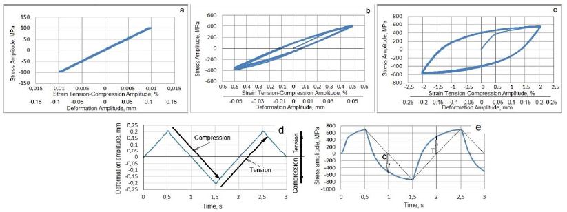
Figure 4: HCVD curves of pure Nb for the viscoelastic tension-compression straining at an amplitude of ε = ±0.1% and corresponding deformation amplitude of v ꞊ ± 0.01 mm in the base length of 10 mm (a), viscoelastic tension-compression straining at strain amplitude of ε = ±0.5% and v ꞊ ± 0.05 mm (b) and at strain amplitude of ε = ±2.0% with the corresponding deformation amplitude of v ꞊ ± 0.2 mm (c). The sample E12 HCVD time-deformation (d) and time-stress (e) curves received at ε = ±2% of strain amplitude. The effect of the elastic-plasticity of Nb on the deflection of the curves during the compression (C) and tension (T) cycles is shown by arrows.
As can be seen in Figure 5, high-purity niobium as well as tantalum EBM ingots contain very large millimeter-sized grains connected by a fully wetted triple grain boundary (GB) (Figure 5a). This width of GBs is in nanometers because the metal is of high purity with thin grain boundaries as shown in the figures. Unfortunately, such large grains contain gas pores with dimensions in micrometers (Figure 5b). Under hydrostatic pressure in the shear region of the IEAP die, these pores are compressed and velded to zero. Such pores and GB defects can be completely repaired by hydrostatic compression and simple shear in the IEAP die. These changes take place in sample for 4 passes of IEAP by BC route (c) and for 12 passes of IEAP by BC route (d), respectively. Microstructural evolution in bulk Ta samples during HCVD are presented in Figure 6. As you can see the microstructure of high purity Ta has GB-s on atomic level [63,68].
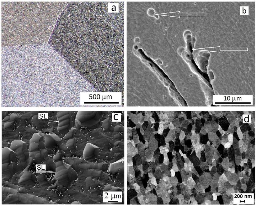
Figure 5: The triple grain boundary (a) and pores (b) in EBM as-cast Nb, and SEM pictures of microstructure evolution via grains fracture by slip lines (SL is shown by arrows) in the shear region of IEAP at von Mises strain of ƐvM=4.62 by BC route (c) and UFG microstructure formed at ƐvM=13.86 (d), respectively.
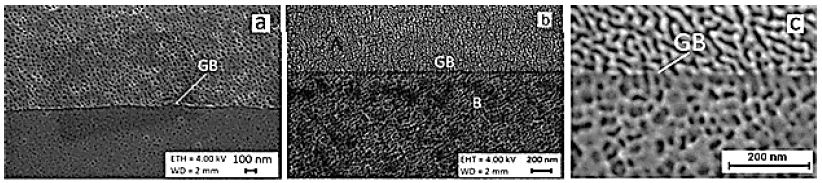
Figure 6: Microstructure evolution of pure Ta processed by HCVD at 5 test series (5 x 20 cycles with strain step-by-step increase up to ε5 ± 2.0%) for 100 tension-compression cycles in sum (a) and atomic level GB-s with different orientations of two grains is presented in (b, c).
The microstructure forming in Nb and Ta samples from initial to 8 passes by BC route for Nb and for 12 passes by BC route for Ta is shown in Figure 7a-7d. The relative frequency of grain size in mm was calculated by by ImageJ software and is presented in Figure 7e-7h. As you can see the grain size of Nb was decreased about 3 times and Ta grain size was decreased about 2.5 times, respectively [67].
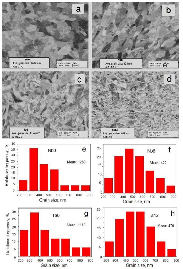
Figure 7: Distribution of grains sizes of Nb (a, b) for initial (Nb0) and after eight passes (Nb8) and Ta (c, d) for initial (Ta0) and after twelve (Ta12) passes by BC route of IEAP. The corresponding grain size measurements were made by ImageJ software (e, f, g, h), respectively.
The microstructure evolution of IEAP Nb sample during HCVD, with a number of 100 cycles for 5 test series is shown in Figure 8a. For comparison, the IEAP Nb after LCF testing for 100 cycles in Figure 8b. The fatigue cracks are formed during LCF. The TEM images of SB-s with a lowered dislocation density at HCVD in Figure 8c and with high dislocation density after LCF of IEAP sample in Figure 8d, respectively [64].
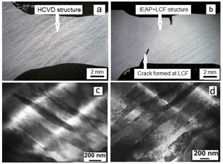
Figure 8: Optical pictures of double-banded microstructure forming in Nb sample at HCVD for 100 cycles (5 x 20 cycles) (a) [64,69] at increased strain amplitude to ε5 ± 2.0% and cracks initiation during LCF testing (b) for 100 cycles of the ECAP sample [69]. TEM images of SB-s with a lowered dislocation density at HCVD (c) and with high dislocation density after LCF of IEAP sample (d).
Young´s Modulus Evolution of Nb at IEAP and at HCVD
The evolution of physical properties during HCVD depends on the microstructure and properties of the metallic material achieved by IEAP treatment, as well as on the strain rate, which depends on the strain amplitude (measured in mm) during HCVD (Figure 4a-4c). As shown in the diagram (Figure 9a), the increase in tensile strength during HCVD at a strain amplitude ε4=±1.5% for all IEAP samples (E2, E4, E6, E8 and E12) with different accumulated von Mises strains is maximum. With an increase in deformation to ε5=±2.0%, the tensile strength of samples E8 and E12 decreased, since these workpieces had a UFG microstructure obtained in IEAP, with higher tensile strength and hardness. During the HCVD process, at a deformation amplitude ε5=±2.0%, softening occurs, since the GS begins to increase during the coalescence process. In these workpieces, Young’s modulus also decreases as they soften (Figure 9b) during HCVD treatment. The Young’s modulus of IEAP-treated samples decreases during the HCVD process as the dislocation density decreases (Figure 8c and 9) [63,64].
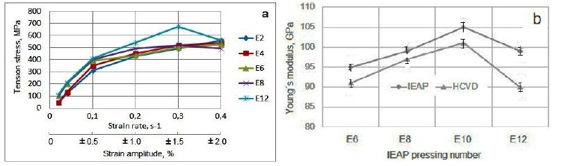
Figure 9: The IEAP samples E2, E4, E6, E8 and E12 tensile strength increases up to strain amplitude ε4=± 1.5%, as well as the strain rate (v=0.3 s-1) increases during HCVD and decrease for E8 and E12 by strain amplitude increase to ε4=±1.5%, (a) and the Yung modulus (b) increases when the von Mises strain increases to ƐvM=11.55 by BC route during IEAP, and the Young’s module decreases in samples E12 by increased von Mises strain up to ƐvM=13.86 by BC route as well by cycles number increase up to 100 cycles during HCVD, respectively.
Ta Physical Properties Evolution at HCVD
The Vickers hardness of Ta was measured, and it was found that with increasing of von Mises strain at IEAP in sample with stepped cross-section, the hardness of Ta increased mainly during the first pressing. By this, the hardness depends on the measurement of orientation to the sample; it is higher in the transverse direction (TD) and lower in cross directions (CS). As shown in Figure 10, a, the Vickers hardness of Ta was increased by increasing the von Mises strain at HCVD. The Vickers microhardness of Ta was increased from 100 HV0.2 to 285 HV0.2, respectively. It should be noted that the methods for measuring hardness according to Martens and Vickers are different. The Marten’s hardness is calculated from the difference between the maximum depth of indentation and after removing the load, when the Vickers hardness is calculated from the length of the diagonal, indentation load and only hardness are measured. The electrical conductivity of Ta (Figure 10b) has similar dependence on strain level and orientation of measure in the heat-treated sample [68].
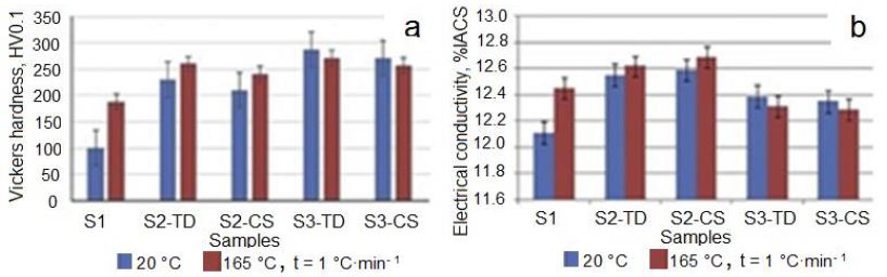
Figure 10: The evolution of Vickers microhardness (a), and electrical conductivity (b) depends on measuring orientation and heat treatment temperature from 20°C to 165°C with a heating rate of 1°C•min−1. TD: Transverse Direction and CS: Cross-Section.
A well-known fact from the scientific literature is that the Young’s modulus is constant in materials at room temperature. This modulus decreases with increasing temperature and increases with increasing the density of materials. Young’s modulus of Ta is about 186 GPa at room temperature and the maximum value is 193 GPA at 10−6 K. As can be seen in Figure 11, this modulus may also be affected by the amount of strain applied to the material (or the number of passes in IEAP) and the change in equivalent strain-stress amplitude during HCVD. The changes of Young’s module in the Ta samples (S1-initial, S2 – 5 pressings of IEAP, ƐvM=5.77, and S3 – 12 pressings of IEAP, ƐvM=13.86) are shown in Figure 11. Before Young module measure the samples were processed by HCVD at strains of ε2=±0.5%, ε3=±1.0%, and ε4=±1.5% for 20 cycles at one strain level. It should be mentioned that Young’s modulus of each sample was measured for three times in the intervals of tensile strains from 0÷0.06% and from 0÷0.1% to ensure about the reliability of results. Was established, that this modulus depends on von Mises strain, strain rate as well on the interval of strain, at which this parameter was measured. When the material is harder, Young’s modulus is higher at the tension in the interval of the strain of 0-0.1% (S2) and when the material is softer, Young’s modulus is higher for 0÷0.06% strain interval (S1) and lowers at 0÷0.1%, respectively [68].
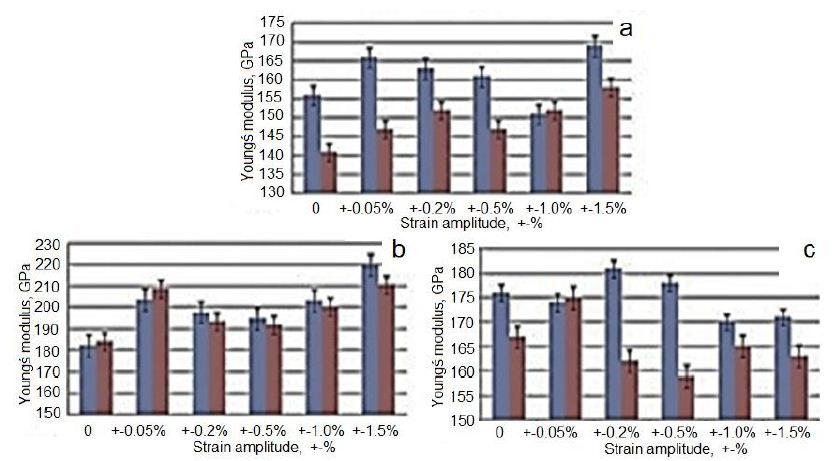
Figure 11: Change of Young’s modulus in Ta at uniaxial tension (measured after IEAP and HCVD) at strain of 0–0.06% (blue) and of 0–0.1% (red) of samples S1 (a), S2 (b) and S3 (c), respectively.
Changes in electrical conductivity and Vickers microhardness in IEAP samples (S1, S2, and S3) were measured with different orientations (Figure 12). These values vary depending on the strain applied during processing or hardness, as well as on the orientation of the measurement, in cross-section (CS) or transverse (TD) direction. As you can see (Figure 12), when the Vickers microhardness is higher, the conductivity is lower when the heating rate is low. In work is shown, that the electrical conductivity depends on the hardness and strength properties of CuCr-alloys. In the works [39] is shown, that the electrical conductivity and Vickers microhardness of CuCr-alloys increase with temperature increase and revealed maximal values at ~550°C. Accordingly, these parameters depend not only on the microhardness because the density of dislocations was lowered during heat treatment. In the present work, the Ta samples were heat treated at a very low heating rate of 1°C·min−1, and the Vickers microhardness and electrical conductivity increased in sample S2 and decrease in sample S3, respectively. The conductivity is expressed as a percentage of the International Standard Annealed Copper (%IACS), which is 5.80 × 10⁷ Siemens/m at 20°C. Results show, that the electrical conductivity varied in dependence on energy associated with dislocations, grain boundaries state, and vacancy concentration in Ta samples during ECAP and HCVD, respectively (Figures 12 and 13) [68,69].
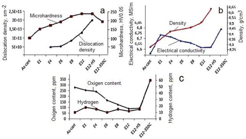
Figure 12: Influence of processing routes as well as microstructure on microhardness, and dislocation density (a), electrical conductivity and density (b), oxygen and hydrogen contents (c) of pure Niobium. Designations: E12-12 passes of IEAP by BC route, H5-five test series by strain rate increase during HCVD, E12-350°C- heat treatment temperature of sample E 12.
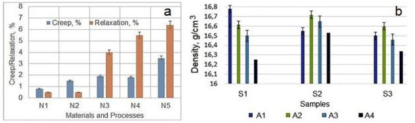
Figure 13: Creep and Relaxation of different materials vs. manufacturing technologies (a). Designations: N1 – By electrical forging (EF) processed Ni-based Fe containing superalloy, N2 – SC Ni-based superalloy, N3 – Cold-drawn pure Cu, N4 – Recrystallized pure Cu, and N5 – ECAP processed nanocrystalline pure Cu [78]. Density evolution of pure Ta processed by IEAP and HCVD (b). Designations: (A4) IEAP processed only, and (A1, A2, and A3) after followed HCVD with different strain amplitude (see Figure 3c) (b).
XRD Investigation of Changes in the Tantalum during EBM, IEAP, and HCVD
Anisotropic deformation during IEAP, and HCVD processes, as well as anisotropic properties in samples, can lead to the formation of anisotropic crystallites and, therefore, anisotropic peak intensities. The X-ray diffraction patterns of the samples: Ta, 2x EBM, Ta, 5x IEAP, Ta, 12x IEAP, and Ta, 5x HCVD are presented in Figure 14. As you can see the X-ray diffraction patterns of the HCVD Ta with compare to EBM and IEAP are differ significantly from other samples. It should be noted that this sample (5x HCVD) had a recrystallized microstructure before HCVD. During HCVD, the microstructure changed, and only one peak appeared in the X-ray diagram at ~ 55.6°. Such an X-ray pattern with a single peak is characteristic of a single-crystal metal and a single-crystal Ni-based superalloy [71]. XRD investigation revealed that at the phase transformation took place at the SPD processing [70,72]. The crystallite size and the dislocation density is possible to determine by X-ray line profile analysis [67,68].
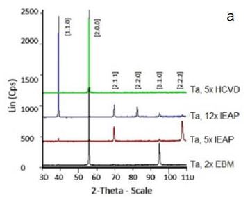
Figure 14: X-ray diffractogram (a) of the Ta samples. Designations: Ta, 2x EBM, initial, Ta, 5x IEAP, Ta, 12x IEAP, and Ta, 5x 5HCVD), respectively.
Influence of HCVD on Wear and Tribological Properties of Nanocrystalline Materials
The specific wear rate (the volume loss per distance per normal load) and coefficient of friction (COF) measurements show their dependence from sample material chemical composition, sample (surface) hardness as well material wear track surface softening/hardening [68,76] during wear testing (Figure 15). Results show that HCV deformed sample in surface was hardened from 77HV0.05 to 90HV0.05 and on the wear track surface from 115 HV0.05 to 126HV0.05, respectively. In this case the surface hardening was induced by cyclic straining and wears track hardening as result of sliding [69].
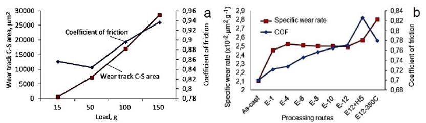
Figure 15: Influence of the load applied on the COF and wear track cross/sectional area of IEAP-12 Niobium (a) and specific wear rate of pure Niobium for different passes number and temperatures for a load of 50 gr (b).
The SEM investigation of the worn track surface shows (Figure 16a) that the UFG microstructure of Nb was abrased by the alumina ball during the dry sliding testing. In our experiments, the wear debris was not removed from the contact zone during testing, which has an influence on the results [35]. The damaged surface of the worn track has wear debris with size of approximately 100 nm. The test results show that the as-cast sample has the lowest amplitude of COF then UFG Nb. The as-cast material has the lowest COF (0.78) and the lowest specific wear rate (2.1, ×10-2×mm2×g-1) when compared to sample E12 (Figure 15b). The maximal COF was obtained for samples after HCV deformation and samples that were tested in directions that crossed the slip band direction. The specific wear rate was significantly increased after heat treatment at a temperature of 350°C (Figure 16) [69].
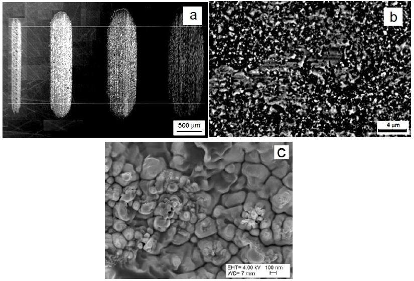
Figure 16: SEM picture of wear track surfaces for 15, 50, 100 and 150 g (a) and UFG Nb wear surfaces with debris formed under a load of 100 g (b), and worn surfaces at high magnification of 100000x of samples after 6 passes of IEAP (c).
When comparing our results with the results presented in previous work, the mass loss decreased remarkably as the number of ECAP passes increased, being affected more by the sliding distance than by the applied load under the experimental conditions. From these data, it has been shown that the wear mechanism was observed to be adhesive and delaminating initially, and an abrasive mechanism appeared as the sliding distance increased. In our experiments, the abrasive wear mechanism did not show any dependence on sliding distance.
Discussion
In the papers, a series of experiments were carried out to study the effect of IEAP and HCVD on the microstructure and properties of metallic materials at room temperature. During the subsequent HCVD, we studied the effect of the strain value during tension-compression with a gradual stepwise increase in strain, strain amplitude, and the corresponding strain rate on the microstructure, functional, physical, chemical, and mechanical properties of the studied Nb and Ta. Then, a series of experiments were carried out to study the influence of the number of deformation cycles, the magnitude of axial deformation, the frequency of cycling, and the strain rate during HCVD and followed heat treatment on the microstructure and evolution of the properties of materials in comparison with their initial state. A comparative analysis was carried out, according to the results of which the following conclusions can be drawn: This owerview study evaluated the impact of a new processing method so called as “Hard Cyclic Viscoplastic Deformation” (HCVD) on microstructure, mechanical, physical, chemical, functional, performance, etc. properties of metallic materials such as niobium, and tantalum. To expand the capabilities of the new processing method, the metal materials Nb and Ta with various structures were tested, such as oligocrystalline, coarse-grained, ultrafine-grained, and nanocrystalline. For pre-treatment, multiple methods of severe plastic deformation were used, such as “Indirect Extrusion Angular Pressing” (IEAP). With this new HCVD test method, it is possible to initiate and study the processes occurring in the microstructure of materials before their destruction. HCVD is based on the application of a cyclic tensile/compressive load by controlled strain amplitude on materials at a constant frequency at a given strain level. In this test method, the main parameters are the strain amplitude of compression/tension in the range from 0.2% to 3.0% with the number of cycles from 20 to 40 for one level of deformation and with a frequency of 0.5 to 2.5 Hz. The rest of the process parameters are set automatically depending on the strength properties of the tested metal material in general.
Conclusions
This review study evaluates the effect of a new processing method, the so-called HCVD, on the microstructure microstructure evolution, and mechanical, physical, chemical, functional, tribological properties change, as well as on phase transformations and interatomic interactions, and service life of various metallic materials. To expand the capabilities of the new processing, metallic materials selected for the study, such as Nb and Ta, with different structures: oligocrystalline, coarse-grained, ultrafine-grained and nanocrystalline were tested.
Using this new test method, it is possible to initiate and study the processes occurring in the microstructure and properties of materials during HCVD before their fatigue failure. HCVD is based on the application of cyclic tensile and compressive loads to materials through a controlled strain amplitude at a constant frequency and a specified level of strain. In this test method, the main parameters are the compression-tensile deformation amplitude in the range from ε=±0.2% to ε=±3.0% with a number of cycles from 20 to 40 for one level of deformation amplitude and with a frequency ƒ=from 0, 5 Hz to 2.5 Hz. The rate of deformation depends on the basic strength parameters of the material. The remaining process parameters are set automatically depending on the strength properties of the metal material being tested as a whole. The main outcomes of this overview work can be summarized as follows:
- The microstructure of Nb and Ta processed by HCVD is significantly different from the microstructure obtained by other SPD methods.
- During IEAP processing of EBM as-cast Nb or Ta samples, the gases pores and any defect in GB-s at hydrostatic compression pressure concurrently with the simple shear stress are eliminated.
- The electrical conductivity in SPD processes decreases with increasing hardness, tensile stress and dislocation density and increases when HCVD is combined with heat treatment and lowering of dislocation density.
- The density of pure Nb increased from 8.27 g/cm3 in the as-cast condition to 8.65 g/cm3 after IEAP and HCVD processing, whit’s is higher than the theoretical (8.55 g/cm3) density.
- The density of pure Ta incrased from 16.26 g.cm-3 to 16.80 g.cm-3 during HCVD.
- During the followed HCVD, the nanostructure (20-90 nm) was formed in shear bands.
- The electrical conductivity during IEAP decreased and during HCVD it increased as a result of the dislocation density decreasing from 5E + 10 cm−2 to 2E + 11 cm−2 since the dislocations are the main obstacles for electrons moving.
- During IEAP, Young’s modulus of Nb was increased to 105 GPa at the von Mises strain ƐvM = 13.86 and then decreased to 99 GPa during the HCVD. The Young modulus (89 GPa) was minimal for sample E12 after HCVD at strain amplitude (Ɛ5= ±2.0%).
- The softening of the material is related to the decrease of Young’s modulus at the HCVD with the increase of the strain rate higher than έ (t) = 0.3 s−1.
- In turn, the decrease in Young’s modulus indicates a decrease in the attraction of interatomic forces in the metal.
- The micromechanical properties differ for IEAP and HCVD samples, as well as for SB and in-body metal. For example, after IEAP for 12 passes by BC route, the SB maximal Vickers nano-hardness was NH = 4.78 GPa and the indentation modulus was Er = 177.7 GPa, respectively.
- During the followed HCVD, these parameters were reduced to NH = 3.29 GPa and Er = 111.4 GPa, respectively.
- The GB width of pure Nb is so small that it is not possible to measure its micromechanical properties by the nano-indentation method used in the present study.
- The gas content in Nb depends on the microstructure condition and it is minimal for UFG pure Nb.
- Compared to the LCF and HCF tests, the HCVD tests require a shorter timeframe.
- Using the HCVD method, it is also possible to study the viability of different metallic materials during operation in aviation, space, and defense under conditions of high load, and close conditions before failure, when the margin of safety is only a few percent.
- Accordingly, this overeview article provides a brief overview of the structure and properties of metallic materials that change as a result of HCVD and thereby extending materials science with new relationships.
Acknowledgment
This research was sponsored by the Estonian Research Council (Grant No. PRG1145).
ORCID Lembit Kommel http: //orcid.org/0000-0003-0303-3353.
References
- Bridgeman PW (1952) Studies of large plastic flow and fracture. McGraw-Hill, New York.
- Segal VM (2002) Severe plastic deformation: simple shear versus pure sheart. Materials Science and Engineering A 338: 331-344.
- Kaveh E, Andrea B, Victor A. Beloshenko, Yan B, et al. (2022) Nanomaterials by severe plastic deformation: review of historical developments and recent advances. Materials Research Letters 10: 163-256.
- Valiev RZ, Estrin Y, Horita Z, Langdon TG, Zehetbauer MJ, et al. (2016) Producing bulk ultrafine-grained materials by severe plastic deformation: Ten year later. JOM 68-4.
- Langdon TG (2013) Twenty-five years of ultrafine-grained materials: achieving exceptional properties through grain refinements. ActaMater 61: 7035-59.
- Estrin Y, Vinogradov A (2013) Extreme grain refinement by severe plastic deformation: a wealth of challenging science. Acta Mater 61: 782–817.
- Bogachev SO, Zavodov V, Naumova EA, Chernenok TV, Lukina EA, et al. (2023) Improvement of strength–ductility balance of Al–Ca–Mn–Fe alloy by severe plastic deformation. Mater Letters 349: 134797.
- Vinogradov A, Estrin J (2018) Analytical and numerical approaches to modelling severe plastic deformation. Progr Mater Sci 95: 172-242.
- 9.Azushima A, Kopp R, Korhonen A, Yang DY, Micari F, et al. (2008) Severe plastic deformation (SPD) process for metals. CIRP Annals-Manufact Techn 57: 716-735.
- Hai Z, Zhiyan H, Wenbin G (2023) Effect of surface severe plastic deformation on microstructure and hardness of Al alloy sheet with enhanced precipitation. Mater Letters 333: 133632.
- Zhaoming Y, Zhimin Z, Xubin L, Jian X, Qiang W.et al. (2020) A novel severe plastic deformation method and its effect on microstructure, texture and mechanical properties of Mg-Gd-Y-Zn-Zr alloy J Alloys and Compounds 822: 153698.
- Kulagin R, Beygelzimer Y, Bachmaier A, Pippan R, Estrin Y (2019) Benefits of pattern formation by severe plastic deformation. Appl Mater Today 15: 236-241.
- Lugo N, Llorca N, Suñol JJ, Cabrera JM (2010) Thermal stability of ultrafine grains of pure copper obtained by equal-channel angular pressing. J Mater Sci 45: 2264-2273.
- Petrov PA, Burlakov IA, Palacheva VV, Zadorozhnyy MY, Golovin IS (2022) Anelasticity of AA5051 alloy subjected to severe plastic deformation. Mater Letters 328: 133191.
- Omranpour B, Kommel L, Garcia Sanchez E, Ivanisenko J, Huot J (2019) Enhancement of hydrogen storage in metals by using a new technique in severe plastic deformation. Key Eng Mater.
- Lugo N, Llorca N, Cabrera JM, Horita Z (2008) Microstructures and mechanical properties of pure copper deformed severely by equal-channel angular pressing and high pressure torsion Materials Science and Engineering A 477: 366-371.
- Conrado RMA, Angelica A, Vladimir S, Dmitri G, Vicente A (2017) From porous to dense nanostructured β-Ti alloys through high-pressure torsion. SCIENTIFIC REPORTS 7: 13618.
- Klaus DL, Xiaojing L, Xi L, Jae KH, Rian J (2021) Dippenaar, Megumi Kawasaki. On the thermal evolution of high-pressure torsion processed titanium aluminide. Materials Letters, 304:130650.
- Zhilyaev A, Langdon T (2008) Using high-pressure torsion for metal processing: Fundamentals and applications, Prog Mater Sci 53: 893-979.
- Han K, Li X, Dippenaar R, Liss KD, Kawasaki M (2018) Microscopic plastic response in a bulk nano-structured TiAl intermetallic compound processed by high-pressure torsion. Mater Sci Eng A 714: 84-92.
- Omranpour B, Kommel L, Sergejev F, Ivanisenko J, Antonov M, et al. (2021) Tailoring the microstructure and tribological properties in commercially pure aluminum processed by High Pressure Torsion Extrusion. Proc Estonian Acad Sci.
- Kommel L, Pokatilov A (2014) Electrical conductivity and mechanical properties of Cu-0.7wt%Cr and Cu-1.0wt% Cr alloys processed by severe plastic deformation. 6th International Conference on Nanomaterials by Severe Plastic Deformation. IOP Conf Series: Mater Eng 63: 012169.
- Higuera-Cobos OF, Cabrera JM (2013) Mechanical, microstructural and electrical evolution of commercially pure copper processed by equal channel angular extrusion. Mater Sci Eng A 571: 103-114.
- Yu M. Murashkin, Sabirov I, Sauvage X, Valiev RZ (2015) Nanostructured Al and Cu alloys with superior strength and electrical conductivity. J Mate Sci 1: 1-19.
- Islamgaliev RK, Nesterov KM, Bourgon J, Champion Y, Valiev RZ (2014) Nanostructured Cu-Cr alloy with high strength and electrical conductivity. J Appl Physics 115: 194301.
- Wei KX, Wei W, Wang F, Du QB, Alexandrov IV (2011) Microstructure, mechanical properties and electrical conductivity of industrial Cu-0.5%Cr alloy processed by severe plastic deformation. Mater Sci Eng A 528: 1478-1484.
- Dobatkin SV, Gubicz J, Shangina DV, Bochvar NR, Tabachkova NY (2015) High Strength and Good Electrical Conductivity in Cu-Cr Alloys Processed by Severe Plastic Deformation, Mater Lett153: 5-9.
- Ma A, Zhu C, Chen J, Jiang J, Song D, S. et al. (2014) Grain refinement and high-performance of equal-channel angular pressing Cu-Mg alloy for electrical contact wire. Metals 4: 586-596.
- Straumal BB, Klimametov AR, Ivanisenko Y, Kurmanaeva L, Baretzky B, et al. (2014) Phase transitions during high pressure torsion of Cu-Co alloys. Mater Letters 118: 111-114.
- Korneva A, Straumal B, Kilmametov A, Chulist R, Straumal P, et al. (2016) Phase transformation in a Cu-Cr alloy induced by high pressure torsion. Mater Char 114: 151-156.
- Straumal BB, Kilmametov AR, Ivanisenko Y, Mazilkin AA, Kogtenkova OA, et al. (2015) Phase transitions induced by severe plastic deformation: steady-state and equifinality. Intern J Mater Research 106: 657-663.
- Mohsen C, Mohammad HS (2018) Effect of equal channel angular pressing on the mechanical and tribological behavior of Al-Zn-Mg-Cu alloy. Mater Char 140: 147-161.
- Chuan TW, Nong G, Robert JK. Wood TG (2011) Wear behavior of an aluminum alloy processed by equal-channel angular pressing. J Mater Sci 46: 123-130.
- Babak OS, Marco AL, Hernandez R, Edgar GS, Lembit K, et al. (2022) The impact of microstructural refinement on the tribological behavior of niobium processed by Indirect Extrusion Angular Pressing. Tribol Intern 167: 107412.
- Kommel L, Põdra P, Mikli V, Omranpour B (2021) Gadient microstructure in tantalum formed under the wear track during dry sliding friction. Wear 466-467: 203573.
- Varvani-Farahani A (2022) Nonlinear kinematic hardening cyclic plasticity. Cyclic Plasticity of Materials. Modeling Fundamentals and Application, Elsevier Series on Plasticity of Materials 2022: 139-174.
- Cyclic Plasticity of Metals, Modeling Fundamentals and Applications, 2021.
- Katerina D. Papoulia M. Rezal H, (2022) Computational methods for cyclic plasticity. Cyclic Plasticity of Metals 227-279.
- Gouzheng K, Qianhua K (2022) Application of cyclic plasticity for modeling ratcheting in metals. Cyclic Plasticity of Metals 325-355.
- Jafar A, Timothy T (2022) Application of cyclic plasticity to fatigue modeling. Cyclic Plasticity of Metals 357-395.
- Radim H, Kyriakos K, Marek P, Zbyněk P (2022) Cyclic plasticity of additively manufactured metals. Cyclic Plasticity of Metals 397-433.
- Agrawal (2014) Low Cycle Fatigue Life Prediction. Int J Emerg Engi Res Tech 2: 5-15.
- Pyttel B, Schwerdt D, Berger C, (2011) Very high cycle fatigue – Is there a fatigue limit? Int J Fatig Adv in Very High Cycle Fatigue 33: 49-58.
- Le Z, Songyun M, Dongxu L, Bei Z, Bernd M (2019) Fretting wear modelling incorporating cyclic ratcheting deformations and the debris evolution for Ti-6Al-4V. Tribol Intern 136: 317-331.
- Calaf J, Sa´nchez M, Bravo PM, D´ıez M. Preciado et al. (2021) Deviations in Yield and Ultimate Tensile Strength Estimation with the Small Punch Test: Numerical Analysis of PreStraining and Bauschinger Effect Influence, Mech Mater 153: 103696.
- Lee SW, Jennings AT, Greer JR (2013) Emergence of enhanced strengths and Bauschinger effect in conform ally passivated copper nanopillars as revealed by dislocation dynamics. Acta Mater 61: 1872-1885.
- Hu X, Jin S, Yin H, Yang J, Gong Y, et al. (2017) Bauschinger effect and back stress in gradient Cu-Ge alloy. Metal Mater Trans A 48-9: 3949-3950.
- Kenk K (2001) On the constitutive modeling of viscoplasticity. Proc. of VIII-th Intern. Conf. Topical Problems of Mechanics, St. Petersburg, Russia 77-86.
- Jong TY, Williams SJ, In SK, Nho KP (2001) Unified viscoplastic models for low cycle fatigue behavior of Waspaloy. Met Mater Int 7: 233–240.
- Li G, Shojaei A (2012) A viscoplastic theory of shape memory polymer fibres with application to self-healing materials. Proc R Soc A 468: 2319-2346.
- Dahlberg M, Segle P (2010) Evaluation of models for cyclic plastic deformation – A literature study. Inspecta Techn. pages 62.
- Sharma P, Diebels S (2023) Modelling crack propagation during relaxation of viscoplastic material. J Mater Sci 58: 6254-6266.
- Kommel L, Veinthal R (2005) HCV deformation – Method to study the viscoplastic behavior of nanocrystalline metallic materials. Rev Adv Mater Sci 10: 442-446.
- Sánchez MD, García VS, Martínez SL, Llumà J (2023) A strain rate dependent model with decreasing Young’s Modulus for cortical human bone. Biom Phys & Eng Expr 9.
- Kommel L (2008) Metals microstructure improving under hard cyclic viscoplastic deformation. Mater Sci Forum 584-586: 361-366.
- Kommel L (2009) Viscoelastic behavior of a single-crystal nickel-based superalloy. Mater Sci.
- Kommel L (2019) Microstructure and properties that change during hard cyclic visco-plastic deformation of bulk high purity niobium. Int J Ref Met Hard Mater.
- Kommel L, Hussainova I, Traksmaa R (2005) Characterization of the viscoplastic behavior of nanocrystalline metals at HCV deformation. Rev Adv Mater Sci 10: 447-453.
- Kommel L, Mikli V, Traksmaa R, Saarna M, Pokatilov A, et al. (2011) Influence of the SPD processing features on the nanostructure and properties of a pure niobium. Mater Sci Forum 667-669: 785-790.
- Kommel L, Rõzkina A, Vlasieva I (2008) Microstructural features of ultrafine-grained copper under severe deformation. Mater Sci (Medžiagotyra) 14: 206-209.
- Kommel L, Hout J, Shahreza BO (Effect of hard cyclic viscoplastic deformation on the microstructure, mechanical properties, and electrical conductivity of Cu-Cr alloy. J Mater Eng Perform.
- Kommel L, Saarna M, Traksmaa R, Kommel I (2012) Microstructure, properties and atomic level strain in severely deformed rare metal niobium. Mater Sci (Medžiagotyra) 18;330-335.
- Kommel L (2019) Microstructure and properties that change during hard cyclic visco-plastic deformation of bulk high purity niobium. Int J Ref Met Hard Mater 79: 10-17.
- Kommel L, Laev N (2008) Mechanism for single crystal refinement in high purity niobium during equal-channel angular pressing. Mater Sci (Medžiagotyra) 14: 319-323.
- Kommel L (2008) UFG microstructure processing by ECAP from double electron-beam melted rare metal. Mater Sci Forum 584-586: 349-354.
- Kommel L, Shahreza BO, Mikli V (2019) Structuration of refractory metals tantalum and niobium using modified equal channel angular pressing technique. Key Eng Mater 799: 103-108.
- Omranpour B, Kommel L, Mikli V, Garcia E, Huot J (2019) Nanostructure development in refractory metals: ECAP processing of Niobium and Tantalum using indirect-extrusion technique. Int J Refr Met Hard Mater 79: 1-9.
- Kommel L, Shahreza BO, Mikli V (2019) Microstructure and physical-mechanical properties evolution of pure tantalum processed with hard cyclic viscoplastic deformation. Int J Ref Met Hard Mater 83: 104983.
- Kommel L, Kimmari E, Saarna M, Viljus M (2013) Processing and propeties of bulk ultrafine-grained pure niobium. J Mater Sci 48: 4723-4729.
- Kommel LA, Straumal BB (2010) Diffusion in SC Ni-base superalloy under viscoplastic deformation. Def Diff Forum.
- Kommel L (2009) Viscoelastic behavior of a single-crystal nickel-base superalloy. Mater Sci (Medžiagotyra) 14: 123-128.
- Kommel LA, Straumal BB (2010) Diffusion in SC Ni-based superalloy under viscoplastic deformation. Defect and Diff Forum 297-301: 1340-1345.
- Kommel L (2015) Effect of hard cyclic viscoplastic deformation on phase’s chemical composition and micromechanical properties evolution in single crystal Ni-based superalloy. Acta Physica Polonica A.
- Kommel L (2004) The effect of HCV deformation on hardening/softening of SPD copper. Ultrafine Grained Materials III 571-576.
- Kommel L (2004) New advanced technologies for nanocrystalline metals manufacturing. 4th DAAAM Conference “Industrial Engineering – Innovation as Competitive Edge for SME”, 195-198.
- Shahreza BO, Sergejev F, Huot J, Antonov M, Kommel L, et al. (2023) The effect of microstructure evolution on the wear behavior of tantalum processed by Indirect Extrusion Angular Pressing. Inter J Refr Metals and Hard Materials 111: 106079.
- Omranpour B, Kommel L, Garcia Sanchez E, Ivanisenko J, Huot J (2019) Enhancement of hydrogen storage in metals by using a new technique in severe plastic deformations. Key Eng Mater.
- Kommel L (2001) The influence of development of new technology and materials on resource of gas turbine engines.