Abstract
In this section, we describe the facile urea-assisted combustion synthesis technique that was used to synthesis of the Dy3+ activated Ca2MgSi2O7 phosphor at the already maintained muffle furnace temperature 600°C. In addition, the characterization studies of the synthesized powder samples are well reported on the basis of their structural, morphological, elemental, and thermal analysis. The synthesized Ca2MgSi2O7:Dy3+ nanophosphor was further characterized by using XRD, FESEM, EDX, and, TL analysis. The obtained XRD pattern indicates tetragonal crystal structures that are compatible with JCPDS card number #79-2425 and recognizes the formation of the desired Ca2MgSi2O7 host without any traces of impurity for confirmation of phase purity. The average crystallite size was estimated using Debye-Scherer’s formula, and was found to be in the range of ~27 nm. It performed a FESEM study to demonstrate exterior morphology. EDX spectra have been employed to establish the sintered phosphor’s elemental composition. The acquired TL glow curve have used to determine the thermal characteristics of the as-synthesized phosphor. Dy3+ doped samples have exposed for 15 min to UV exposure show optimum TL intensity at 112.21°C. With alterations to UV exposure time, it also becomes apparent that the ambient temperature corresponding to the TL peak remains constant. In order to conduct further research on characteristics including activation energy, order of kinetics, and frequency factor, samples with 4 mol% of Dy3+ exposed for varied UV exposure times were chosen. All of these parameters were assessed using the peak shape method. The aforementioned results suggest that an alternative preference for thermoluminescence dosimetry (TLD) and long-lasting applications is the combustion-synthesized Dy3+-doped Ca2MgSi2O7 nanophosphor.
Keywords
Combustion, XRD, FESEM, EDX, Tetragonal, Thermoluminescence (TL), Ca2MgSi2O7:Dy3+
Introduction
Researchers and material scientists have lately been paying special attention to compounds of nanosized luminescent materials of the melilite group doped with rare earth (RE) ions. Alkaline earth silicate phosphors have excellent qualities like high quantum efficiency, abundance, resistance to weathering, affordability, and environmental features. Silicates were also thought to be one of the best host materials for luminescence centers due to their chemical and thermal stability and long persistence times [1]. The reduction of particle size can result in remarkable modifications of some of their bulk properties, nanosized phosphors usually exhibit novel capabilities, such as higher luminescent efficiency [2], and remarkable application potential. The melilites are a large group of compounds characterized by the general formula , where M is a large monovalent or divalent cation, T1 is a small divalent or trivalent cation in tetrahedral, T2 is also a small cation in the other tetrahedral and X is an anion. Afterglow in melilite has already been well documented [3]. In the field of luminescence, the potential utility of lanthanide ions as activators has recently become widely recognized [4]. The afterglow properties of phosphors can be tailored to last for a few seconds to several hours using various activators [5]. Dy3+ is a very effective luminescent centre when utilized as an activator, according to several experimental results of luminescence in some inorganic systems. Furthermore, Dy3+ doped Ca2MgSi2O7 phosphor has been extensively explored for its thermoluminescence properties as a long-lasting phosphor. The persistent emission appears stronger when Dy3+ is added to the host because it is very likely that these ions are involved in electron trapping. With regard to the ability of two Dy3+ ions to substitute for the three ions of the host, it’s possible that the Dy3+ ions will play a role in the creation of defects that act as oxygen vacancies or electron traps [6,7]. Properties like linearity, dose range, energy response, repeatability, stability of stored information, and isotropy are taken into consideration while evaluating the performance of TLD [8]. The preparation of TLDs had good chemical and moisture stability as a result of the addition of SiO2.xH2O and the prudent choice of the chemical form of activators. To analyze the trap centers and trap level in an insulator or semiconductor driven by any radiation-source, TL is one of the most effective techniques [9]. Traps produced by the lattice imperfections play a significant role in the TL characteristics of the phosphors [10].
Accordingly, traps play an essential role in TL research. Understanding the composition of charge carriers’ trapping states is also important. The trapped electrons release energy when heated because they move back to their normal, lower-energy positions. By comprehensively analyzing the TL glow curve, one can learn regarding the trap states and recombination centers [11]. Nowadays, TL materials are widely studied as an effective tool for various applications in the fields of material characterization, archaeological and geological dating, radiation dosimetry, biological applications, age determination, geology or solid-state defect structure analysis, personnel and environmental monitoring etc., being done. Therefore, we suggest that the sintered Dy3+ doped Ca2MgSi2O7 phosphor is a preferable long-persistent phosphor and novel TL material because rare earth dysprosium [Dy3+] ions mainly act as trap centers. In our present investigation, the TL intensity is highly dependent on the concentration of dopants (Dy3+) ions. The maximum intensity of Dy3+ ions was 4 mol% and TL intensity optimum for 15 min UV exposure radiation time and then TL intensity decreases with further UV exposure.
In this article, we have described the synthesis-characterization and thermoluminescence characteristics of prepared the calcium magnesium silicate phosphor (Ca2MgSi2O7:Dy3+) by combustion synthesis utilizing urea (NH2CONH2) as fuel and boric acid (H3BO3) used as flux. Equipped phosphors were characterized and investigated by using X-ray diffractometer (XRD), field emission scanning electron microscopy (FESEM), energy dispersive X-ray spectroscopy (EDX) analysis and Thermoluminescence (TL) analysis in order to structural, morphological, elemental composition, and thermal properties of synthesized powder samples. The aim of this paper is to present the kinetic parameters of the main glow peak (385.21 K) of Ca2MgSi2O7:Dy3+, which have important aspects in the general description of physical characteristics of TL materials, using peak shape (PS) method, namely the order of kinetics (b), symmetry factor (µg), activation energy E (in eV), the frequency factor S (in s−1).
Experimental Analysis
Combustion Synthesis
In order to meet the demands of Material Science and Engineering to create inorganic materials with the appropriate composition, structure, and property, combustion synthesis (CS) has been developed as a standard approach. To sustain a self-propagating high reaction temperature, CS employs extremely exothermic (∆H ≤ 170 kJ/mol) redox (reduction-oxidation) chemicals and combinations, as well as explosive reactions. Metal nitrates serve as the oxidant while urea serves as the fuel in the combustion process. Additionally, this method has the ability to enhance materials, save energy, and protect the environment [12]. The combustion process’ key benefits include rapid heating rates, better processing times, energy efficiency, and the capacity to yield superfine, homogenous, nanocrystalline powders from the combustion products. A vital component of the simple method without a requirement for an expensive high-temperature furnace is the implementation of the enthalpy of combustion to produce and crystallize powders at low calcination temperatures [13]. This technology can effectively replace time-consuming traditional solid-state reaction and sol-gel processing techniques [14]. Numerous refractory materials, such as borides, nitrides, oxides, silicides, intermetallic, and ceramics, have been prepared using this technique.
Powder Sample Preparation
Combustion technique (Figure 1) was successfully employed for the preparation of M2MgSi2O7: Dy3+ (M=Ca) nanophosphor. The starting materials used for the preparation were of Analar grade with high- purity (i.e. 99.99%) and include calcium nitrate [Ca (NO3)2.6H2O], magnesium nitrate [Mg (NO3)2.6H2O], dysprosium nitrate [Dy (NO3)3.5H2O], and fumed silica (SiO2.xH2O). All metal nitrates were considered as sources of oxidizers, boric acid [H3BO3] as flux, and urea [NH2-CO-NH2] was used as fuel. The stoichiometric quantities of the mixture were stirred thoroughly using a magnetic stirrer to obtain a clear solution. The resulting solution was placed in a preheated muffle furnace maintained at 600°C for 5 min. Initially, the solution was thermally dehydrated and later ignited with the liberation of large amount of gases (N2, O2, etc.). Once ignited, the combustion propagates on its own without the need of any external heat. The silicate in a foamy form was obtained finally.
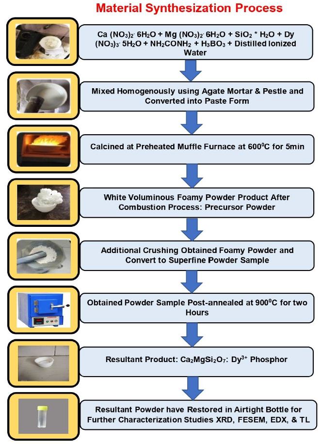
Figure 1: Synthesization of Ca2MgSi2O7: Dy3+ nanometer powder using combustion synthesis technique
After the completion of the process, the product was grinded well using agate mortar pastel to convert into a fine powder form. Further, the sample was post-annealed at 900°C for 2 h under an air atmosphere. In order to obtain white powder, the sample was then despondent cooled to room temperature. The resulting sample was put back together in an airtight bottle for additional characterization investigations such XRD, FESEM, EDX, and TL analysis. Assuming total combustion of the redox mixture for the synthesis of Ca2MgSi2O7 could be written as:
Ca (NO3)2.6H2O + Mg (NO3)2.6H2O + SiO2.xH2O + NH2CONH2 + H3BO3 → Ca2MgSi2O7 + H2O (↑) + CO2 (↑) + N2 (↑) (1)
Ca (NO3)2.6H2O + Mg (NO3)2.6H2O + SiO2.xH2O + Dy (NO3)3.5H2O + NH2CONH2 + H3BO3 → Ca2 MgSi2O7: Dy3+ + H2O (↑) + CO2 (↑) + N2 (↑) (2)
Powder Sample Characterization
Phase structure and composition of the synthesized samples remained categorized by X-ray diffraction arrangement using Bruker D8 advance X-ray diffractometer with Cu-Kα radiation having wavelength 1.5405 Å at 40 kV, and 40 mA. The XRD data were measured over a scattering angle range of 10° to 80°. The surface morphology and EDX analysis performed with the help of FESEM (ZEISS EVO Series EVO 18 microscope) fitted with EDX spectra. Thermoluminescence (TL) glow curves of the UV-irradiated (254 nm) samples were plotted between emitted TL intensity and the corresponding temperature using routine TL set-up Nucleonix TLD reader (1009I) with constant heating rate 5°Cs-1.
Fuel and Oxidizers
Fuel and oxidizers must be utilized during the combustion synthesis process. All metal nitrates are employed as oxidizers, together with boric acid (H3BO3) as a flux and urea (NH2CONH2) as a fuel for combustion. The stoichiometric proportions of all metal nitrates and fuel are calculated using the propellant’s chemistry. With the calculation of oxidizer to fuel ratio, the elements were assigned formal valences as follows: Ca=+2, Mg=+2, Dy=+3, Si=+4, B=+3, C=+4, H=+1, O=-2, and N=0 [15].
Oxidizer and Fuel Ratio
Determining the oxidant to fuel ratio is the most important phase since it is the deciding factor that affects the characteristics of the nanomaterials that will be created. The oxidizer to fuel ratio is termed as “Ψ”, which is defined as following relation [16].
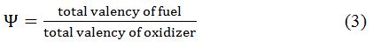
This ratio is very crucial in determining parameters such as reaction temperature and numerous characteristics of nanosized materials such as electrochemical, crystallinity, phase purity and morphology. Additionally, it has been also observed that the particle size of nanomaterial is influenced by the oxidant-fuel ratio. Hence, the oxygen/fuel ratio at which the heat generated by combustion is maximum is 1 [17].
Effect of Fluxes
Some unique fluxes, including Li2CO3 (lithium carbonate), NH4F (ammonium fluoride), NH4Cl (ammonium chloride), BaF2 (barium fluoride), YF3 (Yttrium Fluoride), AlF3 (aluminum fluoride), H3BO3 (boric acid) [18], KCl (potassium chloride), LiF (lithium fluoride), CaCl2 (calcium chloride) [19] etc. are additionally included with the initial precursors to enhance the creation of crystal structures and the properties of the materials, speed up the reaction, and decrease the reaction temperature. The morphological properties of silicate materials are influenced by flux, which additionally enhances the luminous efficiency of powders. The potential benefits and rate of the reaction are influenced by the reactants’ structural characteristics and the reaction circumstances. Any nano- and micro-phosphors’ crystal structure development depends significantly on fluxes. Any formation moves along more quickly because to these fluxes. The final outcome is the synthesis of phosphors with actual chemical structures [20].
Results and Discussion
Powder X-Ray Diffraction Analysis (XRD)
An efficient, necessary, analytical, and nondestructive method for material characterization is powder X-ray diffraction analysis [21]. Diffraction is an X-ray-based technique that provides information on a unit cell’s chemical composition, phase structure, and crystallinity, as well as its microstructure, crystallinity, and stress analysis. It also provides data on its percentage phase composition, inter-planar spacing, and lattice parameters. Figure 1 shows the crystal phase of the phosphor. Comparison of the recorded XRD patterns with the standard JCPDS card number #79-2425 showed good agreement [22]. Akermanite-type structure describes the crystalline structures of synthesized phosphor, which is a member of the tetragonal crystal system with the cell parameters a=b=7.8071 Å, c=4.9821 Å; and α=90°, β=90°, γ=90°, as well as space group is P¯421m (113 space number and D32d space group) and point group is -42 m. Ca2MgSi2O7 crystal structure has a cell volume of 303.663 Å3 and a molar density of 2.944 gm/cm3 [7,23]. The XRD pattern (Figure 2) shows that the sample is single phased, which is consistent with JCPDS file no. 79-2425.
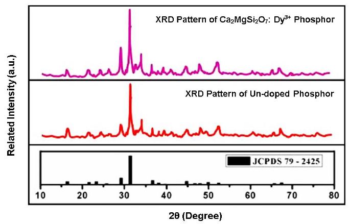
Figure 2: XRD patterns of host & Dy3+ activated Ca2MgSi2O7 phosphor
Estimation of Crystallite Size (D)
The XRD measurement displays a slight shift towards the larger angle in contrast to the standard reference data. From the XRD diffraction peaks, the crystallite size was determined with the help of the Debye-Scherrer empirical formula [24,25].
Debye-Scherrer numerical expression as follows:
![]()
where k is the Scherrer constant, D is the crystallite size for the (hkl) plane, 𝜆 is the wavelength of the incident X-ray radiation [Cu-Kα (1.5405 Å)], β is the full width at half maximum (FWHM) in radiations, and 𝜃 is the corresponding angle of Bragg diffraction. Based on the Debye-Scherrer’s formula, the average particle size obtained from the XRD measurement is ~27 nm, which displays in nano form.
Analysis of Surface Morphology (FESEM) Micrographs
The combustion-synthesized phosphor’s morphology at a 2-micron scale can be seen in the FESEM micrograph (Figure 3), which suggests that the synthesized crystal is in nano form. The particles’ highly agglomerated crystallite shape gives them a frothy appearance. The precursor particles had a spherical shape and were microscopic in size. It also shows aggregated grains, which might be a result of the powder’s extended stay within a combustion furnace. Throughout the combustion reaction process, the particles cluster and get larger. In present case, we have determined the mean value of particle size by Image J software about 20.492 nm.
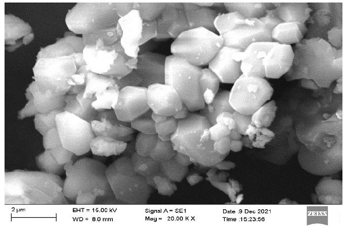
Figure 3: FESEM morphological Image of Dy3+ activated Ca2MgSi2O7 Phosphor with 20.00 K X magnification
Despite the fact that a sample containing stoichiometric proportions of redox mixture boils, goes through dehydration, and then decomposes, creating combustible gases which involves oxides of N2, H2O, and nascent oxygen when heated fast to 600°C. The doped phosphor lattice is able to develop in the ideal environment, which forms when the volatile combustible gases ignite, burn with a flame, and ignite. In addition, this procedure makes it possible to uniformly (homogeneously) dope rare-earth impurity ions in one step. We also anticipate that the particle surface shape may have an impact on the thermal characteristics of these phosphor materials.
Figure 4 shows the electron Image of the synthesized Ca2MgSi2O7: Dy3+ phosphor. It is clearly evident from the picture that the dysprosium ions are well deep trapped in the host crystal lattice sites. That is, they are indicating deeper traps. Dy3+ ions served as hole traps (Dy3+ + hole → Dy4+). Between the lower energy state (ground) and higher energy state (excited) state, Dy3+ ions serve as deep hole trap levels. Dy3+ ions may trap holes or electrons or just to create/modify defects as a result of charge compensation. The deeper traps are highly responsible for the persistent luminescence.
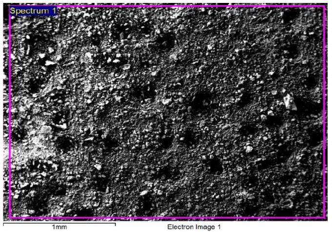
Figure 4: Electron image of synthesized Ca2MgSi2O7: Dy3+ phosphor
Analysis of Energy Dispersive X-ray (EDX) Spectroscopy
Using EDX spectra, the chemical constituents of the powder sample has been determined. Identification and measurement of the elemental composition of sample areas as small as a few nanometers are conventional procedures [26]. In EDX spectra, the presence of Ca, Mg, Si, O and Dy intense peak are present which preliminary indicates the formation of Ca2MgSi2O7: Dy3+ phosphor in Figure 5.
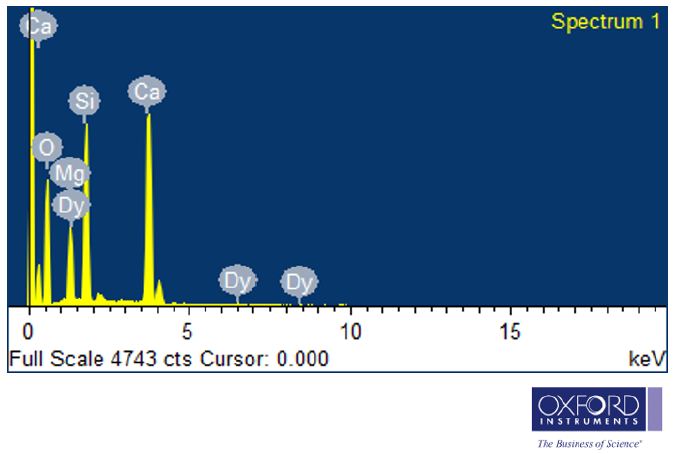
Figure 5: EDX Spectrum of Dy3+ activated Ca2MgSi2O7 phosphor
As well as the existence of dysprosium is clear in their corresponding EDX spectra. Their appeared no other emission apart from calcium (Ca), magnesium (Mg), silicon (Si), oxygen (O), and dysprosium (Dy) in Ca2MgSi2O7: Dy3+ EDX spectra of the phosphor. The elements present in the Weight% and Atomic% also determined which is represented in Table 1.
Table 1: Chemical composition of synthesized Ca2MgSi2O7: Dy3+ phosphor
|
Sr. |
Element |
Weight% |
Atomic% |
| 1. | O K |
54.98 |
71.64 |
| 2. | Mg K |
6.57 |
5.63 |
| 3. | Si K |
13.98 |
10.38 |
| 4. | Ca K |
23.50 |
12.22 |
| 5. | Dy L |
0.97 |
0.12 |
| 6. | Totals |
100.00 |
100.00 |
Thermoluminescence (TL) Analysis
TL Spectra
When some of the energy needed to irradiate a material is used to move electrons to traps, a phenomenon referred to as thermoluminescence (TL). This energy, which was trapped as trapped electrons, is released when the material’s temperature rises, turning the luminescence that results into TL emission [27]. The thermo luminescence dosimetry (TLD) of ionizing radiation, thermo luminescence dosimetry (TLD) for dating applications, and also provides insights on the trap levels are all extensively employed features of the TL technique [28]. The basic goal of TL experiments is to acquire data from an experimental glow curve, or from a series of experimental glow curves, and to analyze that data in order to determine values for all of the parameters with regard to the relevant luminescence mechanisms.The single and strong TL glow curve of UV-irradiated Dy3+ (4 mol%) activated Ca2MgSi2O7 with constant heating rate (5°C/sec) at different UV radiation times (i.e. 5 min, 10 min, 15 min, 25 min, 25 min) is shown in Figure 6. Since the population of trapped electrons in a metastable state reaches a maximum value at a specific time, the TL intensity in this case increases with increasing irradiation time up to 15 min, then decreases with time. From the TL glow curve of Ca2MgSi2O7:Dy3+ it was observed that single broad fitted peak are centered at 112.21°C. The corresponding depth of the trap at 112.21°C should be deeper (high temperature). Deeper traps are highly helpful for increasing the long persistent duration and afterglow process [7]. Therefore, TL data reveal the presence of single trapping levels in Ca2MgSi2O7:Dy3+ phosphor.
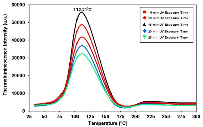
Figure 6: TL glow curve of synthesized Ca2MgSi2O7:Dy3+ phosphor
Concentration Effect of Dy3+ ions
It is obvious that the TL intensity rises with rising Dy3+ concentration, reaches a maximum value at 4 mol%, and then falls with increasing Dy3+ ion concentration. The distance between the activators ions decreases as the activator concentration rises. The ions get involved more frequently, and energy is transferred. On the other hand, the energy that the ions store decreases as the activator concentration rises [7,26]. Consequently, there is an optimum concentration of the activator ions. As is seen from figure the favorable concentration of Dy3+ in Ca2MgSi2O7 nanophosphor is about 4 mole % (relative to Ca2+). The ionic radii of Ca2+, Mg2+, Si4+ and Dy3+ are 1.12 Å, 0.58 Å, 0.26 Å, and 0.97 Å, respectively [29]. When Dy3+ ions doped into Ca2MgSi2O7 host lattice, they may prefer to occupy the Ca2+ crystallographic site rather than Dy3+ site, because the radius of the Dy3+ is very closer to that of the Ca2+ lattice site [30]. A positive centre (hole) is formed when a trivalent metallic ion (such as Dy3+) substitutes a divalent metallic ion in a host lattice. So, Dy3+ ions hardly incorporate into tetrahedral [MgO4] and [SiO4] and only incorporate into [CaO8] anions complexes in host lattice [31]. The traps are released when the phosphor is heated, and the intensity of the thermoluminescence is raised by radiative recombination at the Dy3+ ions.
Peak Shape Method
The most significant glow curve peak’s kinetic parameters are found using the peak shape approach (Figure 7), also referred to as Chen’s empirical method [32]. The kinetic/trapping parameters such as the trap depth or activation energy (E), the order of the kinetics (b), and the frequency factor (s) have a significant impact on the TL characteristics. The area under the curve, the heating rate, the form of the glow curve, and other analytical techniques have all been developed to get TL parameters. The next sections provide a brief overview of the peak shape approach and the findings it produced for the current investigation.
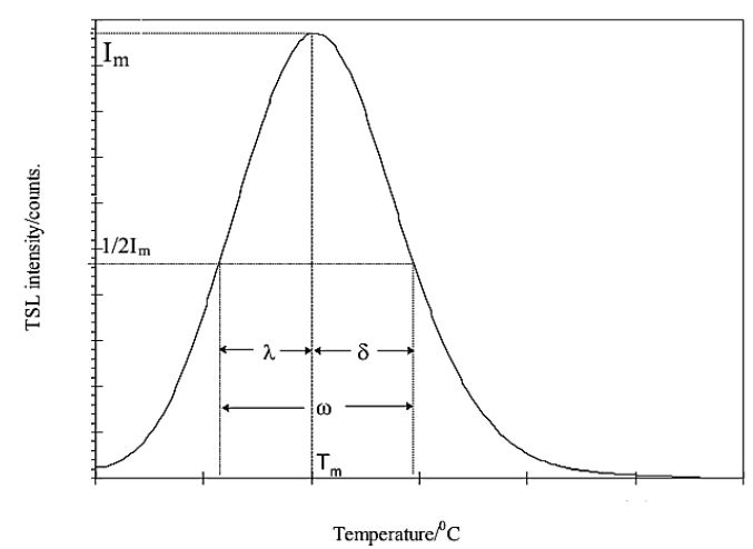
Figure 7: An illustration of a typical thermoluminescent light curve utilizing the peak shape approach
Calculation of Kinetic/Trapping Parameters
[a] Order of kinetics (b)
Recombination of de-trapped charge carriers with their counterparts is referred to as the order of kinetics (b), and the order of kinetics depends on the TL peak shape approach. The TL glow peak of the Ca2MgSi2O7:Dy3+ phosphor TL glow curves was calculated using Chen’s empirical formula.
The geometrical factor μg was calculated as:
![]()
Here, Tm is the temperature corresponding of high peak intensity, whereas T1 and T2 is the ascending and descending part of peak correspond to the full-width at half maxima (FWHM). The TL glow peak divided between first and second order of kinetics of geometric factor defined, first order kinetics (μg)=0.39-0.42, (μg)=0.49-0.52 is the second order kinetics and (μg)=0.43-0.48 is the mixed order of kinetics [33].
The calculated symmetry factor (g) for the single peak was 0.47-0.51, which is close to the value for the second-order kinetics. This demonstrates that the single band’s peaks are of second order. The outcome shows that, in compared to the first-order example, the chance of retrapping carriers is higher after the carriers from the traps corresponding to the single bands were freed [34].
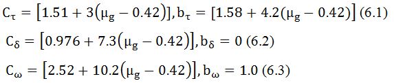
[b] Activation energy (E)
We used the following equation to estimate the depth of the traps, (E). It is calculated by the general formula, which is valid for any kinetics. It is given by,
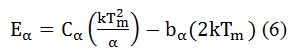
For general order kinetics cα and bα (α=τ, δ, ω) are calculated by following expression,
[c] Frequency factor (S)
After being exposed to ionizing radiation, the frequency factor is a probability that indicates the escape of electrons from the traps. After determining the kinetics order (b) and activation energy (E), the frequency factor (s) has been determined from the following equation and the values of b and E were substituted.
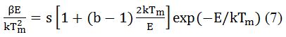
Here, β is heating rate, k is Boltzmann constant, and b is the order of the kinetics, which is 2 in this case. The TL glow curves were recorded by TLD reader (Nucleonix Model 1009I)) with a linear heating rate of 5°C s−1 [35].
Table 2 shows the effects of various UV exposure times, such as 5, 10, 15, 20, and 25 minutes, on the Ca2MgSi2O7:Dy3+ phosphor and several TL kinetic parameters, such as trap energy, symmetry factor, and frequency factor.
Table 2: Values of different Kinetic parameters of the main TL glow peak curves of Ca2MgSi2O7:Dy3+ phosphor calculated from using peak shape method.
|
UV Radiation Time |
(oC) |
(oC) |
(oC) |
E (eV) |
Frequency Factor |
||||
|
5 min |
86.43 |
112.21 |
139.36 |
25.78 |
27.15 |
52.93 |
0.51 |
0.72 |
1.2 × 10⁷ |
|
10 min |
87.33 |
112.21 |
136.10 |
24.88 |
23.89 |
48.77 |
0.49 |
0.77 |
2.87 × 10⁷ |
|
15 min |
87.33 |
112.21 |
136.10 |
24.88 |
23.89 |
48.77 |
0.49 |
0.77 |
2.87 × 10⁷ |
|
20 min |
85.69 |
112.21 |
139.36 |
26.52 |
27.15 |
53.67 |
0.51 |
0.71 |
1.2 × 10⁷ |
|
25 min |
85.69 |
112.21 |
136.10 |
26.52 |
23.89 |
50.41 |
0.47 |
0.66 |
1.1 × 10⁷ |
This method was applied to the cleaned main peak determined by means of trap energy (E), frequency factor (s) and symmetry factor (μg) were calculated using Eqs. (5) and (6). Symmetry factor (μg), average trap energy and frequency factor were found between in the range of 0.47-0.51, 0.66-0.77 eV and 1.1 × 10⁷ to 2.87 × 10⁷ s−1, respectively. Thus, in our case, we obtained the maximum thermo-luminescence [TL] in 15 min UV exposures time. In our case, symmetry factor (μg) is lies between 0.47-0.51, which signs that it is a case of second order kinetics, responsible for deeper trap depth. According to Sakai’s and Mashangva report, he is also reported that a trap depth between 0.65-0.75 eV is very appropriate for long afterglow properties [36,37].
It is obvious that the dysprosium ion, because of its inherent nature, is more to responsible for the hole trap level. That is, the dysprosium ion’s inherent properties enable it to produce a hole trap level as soon as it reaches the host crystal lattice. In a host lattice site, these hole trap levels are trapped extremely deeply. The material has long-lasting properties as a result of these deeper traps.
Conclusion
Tetragonal samples of Ca2 MgSi2O7 with 4 mol% dopant concentration of Dy3+ ions have been successfully synthesized by combustion synthesis technique method at 600°C, which appears to be the most feasible method for their production. For better understanding its spectroscopic and luminescent characteristics, several characterization approaches were investigated. Amorphous structure and nanoscale particle size were determined using XRD and FESEM analyses. The crystallite particle size has been calculated as 27 nm and 20.492 nm. The size of the crystallites has been achieved in the nano order and nano range with considerably greater uniformity. The surface morphology of the particles is shown by the FESEM data to have a flake-like structure, a uniform, homogenous, superfine crystal structure, and to have aggregated firmly. The EDX spectra confirmed the presence of Ca, Mg, Si, O and Dy elements in Ca2 MgSi2O7:Dy3+ phosphor. The TL glow curves are centered at 112.21°C for 15 min UV exposure time, which displays optimum UV exposure time. TL study shows that the optimum Dy3+ concentration was found for 4 mol%. The probability of recapturing released charge carriers before recombination is supported by the second order kinetics. The long after glow process is being enhanced considerably by Dy3+ ions. The activation energy of Ca2 MgSi2O7:Dy3+ was found to be 0.66-0.77 eV. On the basis of the value of the activation energy, we have suggested that the Combustion-synthesized Ca2MgSi2O7:Eu2+, Dy3+ phosphor is an excellent thermoluminescent material and a more efficient long persistent material. It may highly applicable for TL dosimetry and long persistent applications.
Future Scope of This Work
The advancement of energy-efficient transmission, storage, and generating technologies using nanomaterials has significantly enhanced the effectiveness of both conventional and renewable energy sources. The thermoluminescence properties of nanomaterials have highly applicable in archeological dating, forensic science, geology, medical dosimetry, environmental radiation, oncology radiation, biological science, radiation physics, medicine, neutron-dosimetry, UV radiation monitoring, high-level photon dosimetry radiation. Radiation therapy or radio-therapy have used in a cancer disease treatment and kill cancer cells. As-synthesized Ca2MgSi2O7: Dy3+ phosphor is an excellent thermoluminescent material and a more efficient long persistent material.
It is highly applicable in TL radiation dosimetry applications for personnel and environmental monitoring. The luminescent features of biomaterials have prospective applications in different areas such as DNA transplantation of tumor in the field of biological science, signal processing or image recognition in the field of computer science and information technology, drug delivery in the field of pharmaceutical science, and in the field of nutrition therapy, chemotherapy, as well as in the field of tissue engineering and bone-tissue engineering.
Acknowledgement
We gratefully acknowledge the kind support for the facility of XRD, FESEM, and EDX analysis Dept. of Metallurgical Engineering, NIT Raipur (C.G.). Authors are also thankful to Dept of physics, Pt. Ravishankar Shukla University, Raipur (C.G.) for providing us the facility of thermoluminescence (TL) analysis. We are also heartily grateful to Dept. of physics, Dr. Radha Bai, Govt. Navin Girls College Mathpara Raipur (C.G.), providing the facility of muffle furnace and other essential research instruments
Competing Interests
Authors have declared that no competing interests exist in this present research investigation.
Authors Contribution
Both authors contributed to the completion of this work. Author Dr. Shashank Sharma undertakes the manuscript designed and conducted the entire experiments and characterization studies, collected and analyzed the research data, and prepared the entire manuscript draft as well as supervised the results-discussion. Similarly, author Dr. Sanjay Kumar Dubey has properly checked the spelling mistake, punctuation, grammatical error, conceptualization, writing, review, editing and helped in sample preparation. Both authors read and approved the final manuscript.
References
- Prasannakumar JB, Vidya YS, Anantharaju KS, Ramgopal G, Nagabhushana H, et al. (2015) Bio-mediated route for the synthesis of shape tunable Y2O3: Tb3+ nanoparticles: photoluminescence and antibacterial properties. Spectrochimica Acta Part A: Molecular and Biomolecular Spectroscopy 151: 131-140.
- Hong DS, Meltzer RS, Bihari B, Williams DK, Tissue BM (1998) Spectral hole burning in crystalline Eu2O3 and Y2O3: Eu3+ Journal of Luminescence 76: 234-237.
- Gong Y, Wang Y, Jiang Z, Xu X, Li Y (2009) Luminescent properties of long-lasting phosphor Ca2MgSi2O7: Eu2+. Materials Research Bulletin 44: 1916-1919.
- Cai J, Pan H, Wang Y (2011) Luminescence properties of red-emitting Ca2Al2SiO7: Eu3+ nanoparticles prepared by sol-gel method. Rare Metals 30: 374-380.
- Talwar GJ, Joshi CP, Moharil SV, Dhopte SM., Muthal PL, et al. (2009) Combustion synthesis of Sr3MgSi2O8: Eu2+ and Sr2MgSi2O7: Eu2+ Journal of Luminescence 129: 1239-1241.
- Dutczak D, Milbrat A, Katelnikovas A, Meijerink A, Ronda C, et al. (2012) Yellow persistent luminescence of Sr2SiO4: Eu2+, Dy3+. Journal of Luminescence 132: 2398-2403.
- Sharma S, Dubey SK (2022) Significant Contribution of Deeper Traps for Long Afterglow Process in Synthesized Thermoluminescence Material. Journal of Mineral and Material Science 3: 1-6.
- Mckeever SWS (1985) Thermoluminescence of Solids, Cambridge University Press. London New York.
- Vij DR (1993) Thermoluminescence materials, PTR Prentice-Hall, Inc. A Simon a Schuster Company, Englewood Cliffs, New Jersey 7632.
- Yuan ZX, Chang CK, Mao DL, Ying W (2004) Effect of composition on the luminescent properties of Sr4Al14O25: Eu2+,Dy3+ Journal of Alloys and Compounds 377: 268-271.
- Kiisk V (2013) Deconvolution and simulation of thermoluminescence glow curves with Mathcad. Radiation Protection Dosimetry 156: 261-267.[crossref]
- Aruna ST, Mukasyan AS (2008) Combustion synthesis and nanomaterials. Current opinion in Solid State and Materials Science 12: 44-50.
- Ekambaram S,Patil KC (1995) Synthesis and properties of rare earth doped lamp phosphors. Bulletin of Materials Science 18: 921-930.
- Toniolo JC, Lima MD, Takimi AS, Bergmann CP (2005) Synthesis of alumina powders by the glycine-nitrate combustion process. Materials Research Bulletin 40: 561-571.
- Dubey SK, Sharma S, Diwakar AK, Pandey S (2021) Synthesization of Monoclinic (Ba2MgSi2O7: Dy3+) Structure by Combustion Route. Journal of Materials Science Research and Reviews 8: 172-179.
- Liu G, Li J, Chen K (2010) Combustion synthesis. Handbook of Combustion: Online 1-62.
- Kingsley JJ, Patil KC (1988) A novel combustion process for the synthesis of fine particle α-alumina and related oxide materials. Materials Letters 6: 427-432.
- Park B, Lee S, Kang J, Byeon S (2007) Single-Step Solid-State Synthesis of CeMgAl~ 1~ 1O~ 1~ 9: Tb Phosphor. Bulletin-Korean Chemical Society 28: 1467.
- MORAIS VRD, LEME DDR, Yamagata C (2018) Preparation of Dy3+-doped calcium magnesium silicate phosphors by a new synthesis method and its luminescence characterization.
- Sharma S, Dubey SK (2021) The significant properties of silicate based luminescent nanomaterials in various fields of applications: a review. International Journal of Scientific Research in Physics and Applied Sciences 9: 37-41.
- Bates S, Zografi G, Engers D, Morris K, Crowley K, et al. (2006) Analysis of amorphous and nanocrystalline solids from their X-ray diffraction patterns. Pharmaceutical Research 23: 2333-2349.[crossref]
- JCPDS (Joint Committee on Powder Diffraction Standard) PDF File No. #79-2425.
- Sharma S, Dubey SK (2023) Enhanced Luminescence Studies of Synthesized Ca2MgSi2O7: Ce3+ Phosphor. COJ Biomedical Science and Research 2: 1-9.
- Birks LS, Friedman H (1946) Particle size determination from X‐ray line broadening. Journal of Applied Physics 17: 687-692.
- Scherrer P (1918) Bestimmung der Grösse und der inneren Struktur von Kolloidteilchen mittels Röntgenstrahlen. Nachrichten von der Gesellschaft der Wissenschaften zu Göttingen, mathematisch-physikalische Klasse 98-100.
- Sharma S, Dubey SK (2022) “Specific Role of Novel TL Material in Various Favorable Applications.” Insights in Mining Science & Technology 3: 1-9.
- Vij DR (1998) Luminescence of solids, New York.
- Jüstel T, Lade H, Mayr W, Meijerink A, Wiechert DU (2003) Thermoluminescence spectroscopy of Eu2+ and Mn2+ doped BaMgAl10O17. Journal of Luminescence 101: 195-210.
- Shannon RD (1976) Revised effective ionic radii and systematic studies of interatomic distances in halides and chalcogenides. Acta Crystallographica Section A: Crystal Physics, Diffraction, Theoretical and General Crystallography 32: 751-767.
- Sharma S, Dubey, SK (2022) Importance of the Color Temperature in Cold White Light Emission of Ca2MgSi2O7: Dy3+ Journal of Applied Chemical Science International 13: 80-90.
- Jiang L, Chang C, Mao D (2003) Luminescent properties of CaMgSi2O6 and Ca2MgSi2O7 phosphors activated by Eu2+, Dy3+ and Nd3+. Journal of Alloys and Compounds 360: 193-197.
- Chen R (1969) Thermally stimulated current curves with non-constant recombination lifetime. Journal of Physics D: Applied Physics 2: 371.
- Sharma S, Dubey SK (2023) Enhanced Thermoluminescence Properties of Synthesized Monoclinic Crystal Structure. Global J Mater Sci Eng 5: 146.
- McKeever SW (1988) Thermoluminescence of solids (Vol. 3) Cambridge University Press.
- Chen R (1969) Glow curves with general order kinetics. Journal of the Electrochemical Society 116: 1254-1257.
- Mashangva M, Singh MN, Singh TB (2011) Estimation of optimal trapping parameters relevant to persistent luminescence.
- Sakai R, Katsumata T, Komuro S, Morikawa T (1999) Effect of composition on the phosphorescence from BaAl2O4: Eu2+, Dy3+ Journal of Luminescence 85: 149-154.