Abstract
Background: The biomechanics of clear aligner (CA) orthodontics in maxillary first premolar extraction cases with space closure are not yet fully understood. This study aimed to investigate the biomechanics of en-mass retraction(EMR)(0.2mm) of maxillary anterior teeth after first premolar extraction using a CA system, employing the finite element model (FEM). The goal was to provide a more comprehensive theoretical foundation for both clear aligner treatment (CAT) and its design for cases with EMR of maxillary anterior teeth.
Methods: Using Cone-Beam Computed Tomography (CBCT), an adult volunteer with normal occlusion who met the modelling standards in the Stomatological Hospital of Nankai University was scanned. Models including a maxillary dentition without first premolars, the periodontal ligament (PDL), alveolar bone, and a CA were established using Mimics 17.0, Geomagic Studio 12.0, and UG NX software packages. ANSYS Workbench 19.0 was used for preprocessing, parametric design, mesh generation, and data analysis.
Results: The maxillary anterior teeth exhibited distal and palatal tipping, accompanied by extrusion and torque loss. Mesial tipping, intrusion and anchorage loss of the posterior teeth were observed. This is a typical roller coaster effect (RCE) in orthodontics. Stress distribution within the PDL and alveolar fossa was concentrated in the cervical and apical regions, aligning with the trend of tipping tooth movement. The entire CA showed tendencies to dislocate and bow bend with more pushing stress distribution on the labial aspect of the CA’s anterior region and mesial wall of the canine area suggesting a pushing device. In addition, the premolar extraction junction area and posterior regions were identified as primary stress-bearing components.
Conclusion: In treatments involving premolar extraction using the CA technique, it is crucial to implement strategies to counteract RCE caused by CA bow bending during retraction. Moreover, it is imperative to enhance torque control in the anterior teeth and protect anchorage in the posterior teeth.
Keywords
EMR, Biomechanics, CA, RCE, FEM
Introduction
Both fixed and removable orthodontic appliances correct malocclusion, characterized by uneven teeth or misalignment of dental arches, through tooth movement using the premolar extraction protocol in most cases [1-3]. This approach poses challenges to controlling precise tooth movement in three-dimensional directions [4]. In 1999, Align Technology, Inc. (San Jose, CA, USA) introduced clear aligner treatment (CAT), leveraging computer-aided design (CAD) and manufacturing. Based on virtual tooth movement designs created by CAD software [5], aligners incrementally induce tooth movements through a series of aligners to achieve intended outcomes [6]. CAT offers several advantages over traditional wire-bracket systems, such as aesthetic appeal, reduced discomfort, lower forces, and improved time efficiency with fewer visits and emergencies [6]. However, the efficacy of CAT, particularly in complex malocclusions requiring extractions, especially for premolar extraction protocol, is subject to debate due to unclear force interplay and biomechanics mechanisms [7-12]. Unlike fixed orthodontics where tooth movement results from wire-bracket interactions, CAT relies on force from aligner-teeth shape mismatches [11], and the complete coverage of tooth crowns by aligners complicates the assessment of force and moment application on the tooth [12]. Although introducing auxiliary devices such as attachments improves the control of the clear aligner (CA) on tooth movements, its effectiveness remains unsatisfactory. In CAT, normally, treatment strategies adopt a step-by-step movement to reduce side effects, such as roller coaster effect (RCE) [13,14] in premolar extraction cases. Although this method is effective, it inevitably leads to an extension of the treatment cycle. To enhance efficiency and shorten the treatment span, the technique of en-mass retraction (EMR) has become a future trend in the development of CAT. EMR is particularly suitable for cases requiring minimal to moderate anchorage but is also frequently used in most cases to close small gaps in the progress and refinement stages of treatment. From these perspectives, EMR will play an important role in future CAT and be used in many cases. However, the biomechanics of EMR in practice are not fully understood, and the related side effects, as well as how to effectively prevent and manage them, have not been fully resolved. Therefore, investigating the biomechanics of EMR, along with gaining a deeper understanding of the biomechanics of CAT to prevent unwanted tooth movements, is crucial. Such endeavors establish a significant foundation for enhancing clinical CAT and supporting further scientific studies.
Finite element model (FEM) analysis, known for its non-invasive precision, is crucial in examining mechanical impacts of orthodontic devices (including clear aligners) and quantifying stresses and movements in orthodontic studies [15-17]. This study aims to elucidate the biomechanical principles and side effects of EMR without auxiliary equipment, providing a scientific basis for optimizing CAT. The objectives are to prevent unwanted tooth movements, refine treatment planning, reduce duration, minimize patient discomfort, establish a foundation for future research, and contribute to the advancement of CA orthodontics.
Methods
Model Construction
Jaw and Dentition Scanning: The jaw and dentition of the volunteer were scanned using cone-beam computed tomography (CBCT) (EW00-VATECH, South Korea). The exposure settings were as follows: 15×15 cm field of view, 10.0 mA, 90 kVp, total scanning time of 15.0 seconds, effective radiation time of 4.0 seconds, and voxel size of 0.3 mm. During image acquisition, the subject was seated upright, and an ear rod was used to stabilize their heads so that the Frankfort horizontal plane was parallel to the floor. The acquired Digital Imaging and Communications in Medicine (DICOM) format data were imported into Mimics 17.0 (Materialise, Belgium). The alveolar bone and teeth data were extracted using threshold segmentation in the 900–3095 HU range. Following grey value selection, region growing, noise reduction, and binarization, a three-dimensional (3D) model of the maxillary dentition and jaw was developed. This model was refined, smoothed, and glossed in Geomagic Studio 12.0 (Raindrop, USA) to create a high-precision solid 3D model. It was then imported into UG NX 12.0 (UGS, USA) to solidify the geometric structure. The bilateral maxillary first premolars were removed in this software to create premolar spaces, and the dentition without first premolars was remarked as initial dentition M. High-precision geometric models were obtained (Figure 1), serving as the foundation for subsequent experimental models, ensuring no software error superposition. According to the scientific literature, the roots of the teeth are spread uniformly along the outer surface to obtain the PDL (continuous 0.25 mm) [7]. Research indicates that tooth movement per step in CAT ranges from 0.20 to 0.33 mm, typically designed as 0.2 mm per step in both clinical and scientific studies [18]. Therefore, based on the initial dentition (M), the maxillary anterior teeth were retracted bodily by 0.2 mm in the sagittal direction (Consistent with the Z-axis), and the obtained new dentition was marked as N [19]. Next, N was imported into Geomagic Studio 12.0 software to process the space between every two teeth separately. The outer surface of the crown was extracted as the inner surface of the CA and sliced through the boundary curve of the crown. The template thickness was 0.5 mm, and the Boolean operation was carried out with N to obtain a solid geometric model of CA (Figure 1). These solid models were assembled (Figure 1) and imported into ANSYS Workbench 19.0 (ANSYS, USA) for parameter setting, mesh generation, loading, and other simulations. The EMR of the maxillary anterior teeth was simulated with a bodily displacement of 0.2 mm (per aligner) in the sagittal direction. The postprocessing function was used to evaluate the data. For the baseline, no auxiliary devices (like attachments) were introduced in this study. All experimental procedures conformed to the guidelines of the Stomatological Hospital Medical Ethics Committee of Nankai University, and informed consent was obtained from the volunteer.
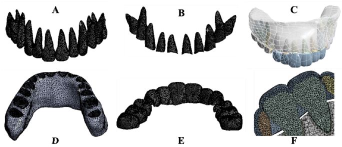
Figure 1: The three-dimensional finite element models of maxillary teeth, alveolar bone, PDL and CA. Maxillary teeth (A), Periodontal ligament (B), Assembly (C), Maxillary alveolar bone (D), Maxillary clear aligner (E), Assembly section (F).
Material Properties, Interaction, and Boundary-Settings
The model substances were defined as continuously homogeneous and isotropic, and the orbital floor of the maxillary alveolar bone served as a fixed constraint. A frictional interaction between the crown and the CA was set, with a coefficient of 0.2. Binding restrictions were applied between the teeth, PDL and alveolar bone. The elastic moduli for the alveolar bone, teeth, PDL, and CA were set to 2,000, 20,000, 0.05, and 450 Mpa, respectively, with Poisson’s ratios of 0.30, 0.30, 0.35 and 0.40, respectively [20].
Mesh Division and Results
The CA used triangular six-node shell elements, and the other models adopted tetrahedral ten-node elements, both of which have properties such as plasticity, wiggling ability, large deformation, and high tensility. Node counts for the entire model, alveolar bone, teeth, PDL, and CA were 1138046, 257810, 569455, 117193, and 193598, respectively, with component counts of 726808, 162931, 390852, 58026, and 114999, respectively.
Coordinate System Setting
The global coordinate system was used to define the direction of x, y, and z axes. The X-axis is positively directed to the patient’s left side, parallel to the occlusal plane. The Z-axis positively directed perpendicularly to the X-axis towards the tooth root apex. The Y-axis, positive in the direction perpendicular to both X- and Z-axes, pointed towards the incisor. Opposite directions corresponded to their respective negatives.
Calculation and Analysis
The bilaterally symmetrical model was analyzed using the right maxillary model. The analysis focused on tooth displacement, periodontal tissue stress distribution, CA deformation, and CAbearing stress distribution.
Results
Maxillary Dentition, PDL, CA, 3D-FEM
High-quality 3D FEMs of the maxillary teeth, PDL, alveolar bone, CA, along with their assembly were obtained in this study (Figure 1).
Initial Displacement Trend and Value of Teeth
Figure 2 shows the teeth displacement trend and Table 1 presents measurements of the incisor edge midpoint, canine cusp, buccal cusp of the second premolar, and both buccal and palatal cusps of the first molar, as well as the tooth root apex. The initial displacement value of the maxillary teeth corresponded with the movement trend, exhibiting tipping movements in the opposite direction of the crown and root. The incisor crown has tipped distally, and the palatally root is inclining labially and mesially. A similar pattern was observed in the canine. The central incisor, lateral incisor, and cuspid showed increasing distal tipping, decreasing palatal tipping, and occlusal extrusion. Posterior crowns tipped mesially and palatally, with roots on the distal and buccal sides. Vertically, the second premolar was intruded, the mesial cusp of the first molar was intruded, while the distal cusp extruded. These tooth movement patterns align with a typical side effect of RCE. RCE occurs during canine retraction with a light, flexible NiTi (nickel-titanium) wire. Due to its insufficient stiffness, the wire bends under retracting forces, causing the molar and premolar crowns to tip mesially and extrude distally. This bending leads to the canine crown tipping distally, which, influenced by the orientation of the canine bracket, results in the extrusion of the incisors and a deepened bite [21]. Significant 3D movement was also observed in the lateral incisor, along with notable buccal movement of the cuspid and palatal movement of the second premolar.
Table 1: Initial displacement of maxillary anterior teeth on X,Y and Z axes(mm)
|
Tooth |
Position | X-axis | Y-axis |
Z-axis |
| Central incisor | crown |
-0.02597 |
–0.13336 |
-0.23133 |
| root tip |
0.00724 |
0.04616 |
-0.08820 |
|
| Lateral incisor | crown |
-0.21951 |
-0.22496 |
-0.15497 |
| root tip |
0.08623 |
0.07647 |
-0.05400 |
|
| Canine | crown |
-0.27002 |
-0.03771 |
-0.01360 |
| root tip |
0.03566 |
0.03715 |
-0.02142 |
|
| Second premolar | crown |
0.08141 |
0.30111 |
0.01008 |
| root tip |
-0.03286 |
-0.13297 |
-0.00267 |
|
| First molar | Mesial buccal cusp |
0.05133 |
0.03523 |
0.02731 |
| Mesial lingual cusp |
0.04913 |
0.02863 |
0.01610 |
|
| Distal buccal cusp |
0.04857 |
0.02082 |
-0.02108 |
|
| Distal lingual cusp |
0.07070 |
0.02105 |
-0.02410 |
|
| Mesial apex |
-0.04498 |
-0.02054 |
0.00088 |
|
| Distal apex |
-0.04719 |
-0.01927 |
-0.00143 |
|
| Palatal apex |
-0.02016 |
-0.00962 |
-0.00055 |
Note: The left side of the X-axis is positive; the direction of the central incisor on the Y-axis is positive; the direction of the apex of the tooth on the Z-axis is positive.
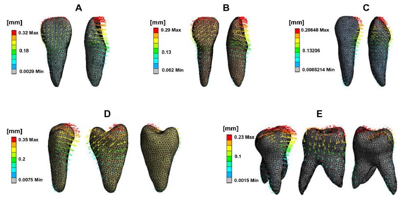
Figure 2: Initial displacement trend of maxillary teeth. Central incisor (A), Lateral incisor, Canine (B), Second premolar (C), First molar (D). The front, middle, and back rows represent the palatal, mesial, and distal views, respectively. The direction and length of the arrows indicate the displacement direction and magnitude, as well as the deformation extent.
Stress Distribution of Periodontal Tissue
Figure 3 depicts PDL stress concentrated in the cervical and apical regions of the maxillary teeth. Anterior teeth stress is primarily located on the palatal and distal surfaces in cervical areas and the buccal and mesial zones in apical regions. Posterior teeth stress predominated in the mesial cervical areas and the distal apical regions. Figure 4 illustrates PDL’s tensile and compressive stresses, defined as the negative and positive maximum principal stress, respectively. Incisors exhibited compressive stress on the palatal-distal cervical and labial-mesial apical regions, and tensile stress on the labial-mesial cervical areas and palatal-distal apical areas. The canines showed similar stress patterns as the incisors. For the posterior teeth, compressive stress appeared in the mesial cervical and distal apical regions, while tensile stress was found in the distal cervical and mesial apical areas. Notably, in the lateral incisor, stress concentrations were also observed in the labial and mesial cervical surfaces and palatal and distal apical regions. According to Figure 3 and Table 2, the highest stress appeared in the anterior teeth’ distal and palatal cervical regions, the mesial cervical regions of the second premolar and the first molar, and the apical areas. Figure 5 shows stress in the alveolar socket localized in the cervical regions and not evident in other areas. Table 2 indicates that the absolute value of peak tensile stress was more significant than that of compressive stress, with high stress on both sides of the extraction region. Moreover, the stress in posterior teeth was evidently greater than that in anterior teeth.
Table 2: Comparison of peak PDL stress in maxillary teeth (MPa)
|
Tooth |
Equivalent stress | Tensile stress |
Compressive stress |
| Central incisor |
0.025 |
0.013 |
-0.007 |
| Lateral incisor |
0.023 |
0.020 |
-0.006 |
| Canine |
0.037 |
0.018 |
-0.013 |
| Second premolar |
0.042 |
0.037 |
-0.011 |
| First molar |
0.046 |
0.021 |
-0.008 |
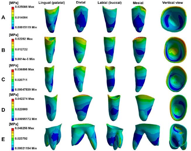
Figure 3: The equivalent stress distribution of PDL in maxillary. Central incisor (A), Lateral incisor (B), Canine (C), Second premolar (D), First molar (E).
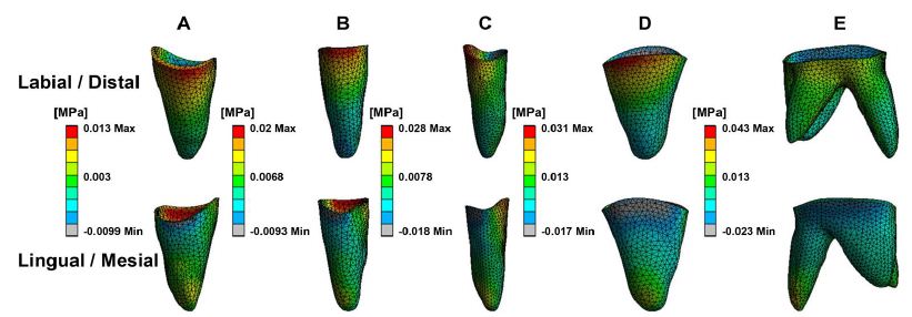
Figure 4: The tensile and compressive stress of periodontal ligament in maxillary teeth. Central incisor (A), Lateral incisor (B), Canine (C), Second premolar (D), First molar (E).
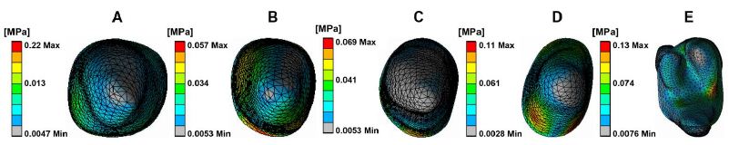
Figure 5: The equivalent stress distribution of alveolar socket. Central incisor (A), Lateral incisor (B), Canine (C), Second premolar (D), First molar (E).
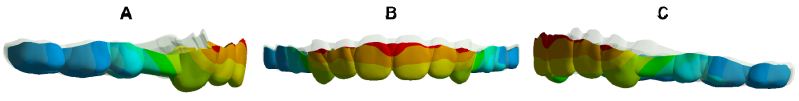
Figure 6: Overlay of CA: The grey is the original CA, and the colour is the stretched CA. Right (A), Front (B), Left (C).

Figure 7: CA deformation trend. Anterior region (A), Posterior region (B). The direction and length of the arrows indicate the displacement direction and magnitude, as well as the deformation trend.

Figure 8: The equivalent stress distribution of CA. Labiolingual side of anterior area (A and B), Buccal and palatal sides of posterior area (C and D).
CA Displacement Deformation and Stress Distribution
Figure 6 indicates that the entire CA exhibited typical bow bending, characterized by distal-palatal tipping of the anterior region with occlusal disengagement, and the posterior part shifting palatalmesial and detaching occlusally. Figure 7 illustrates the propensity for deformation and detachment of the CA. The mesial region of the second premolar was intruded, the second molar area was poorly dislocated, and the extraction segment was the most severely deformed. The deformation prosperities of CA directly contribute to RCE. Table 3 reveals the average movement values of the mesial, distal, and middle edges of CA in each tooth location on the X-, Y-, and Z-axes, reflecting the displacement of CA and the 3D shift of CA margins. As per Figure 8, CA stress was primarily concentrated at the junctions, widespread in the posterior region, with the highest peak value at the mesial junction of the second premolar. Stress was almost absent on the palatal side of the CA incisor region and the distal side of the CA canine area, but prevalent in the labial area of the CA incisor region and mesial region of the CA canine area, suggesting that the CA functions as a pushing orthodontic appliance.
Table 3: Initial displacement of CA on X, Y and Z axes (mm).
|
Position |
X-axis | Y-axis | Z-axis | |||
| labial/buccal | lingual/palatal | labial/buccal | lingual/palatal | labial/buccal |
lingual/palatal |
|
| Central incisor |
-0.014 |
-0.016 | 0.128 | 0.174 | -0.047 |
0.061 |
| Lateral incisor |
-0.083 |
-0.097 | 0.095 | 0.173 | -0.024 |
0.051 |
| Canine |
-0.053 |
-0.125 | -0.167 | -0.177 | -0.025 |
0.037 |
| 1st premolar |
-0.009 |
-0.003 | 0.074 | 0.118 | -0.019 |
-0.052 |
| 2nd premolar |
-0.016 |
-0.075 | 0.209 | 0.181 | -0.029 |
-0.040 |
| 1st molar |
-0.015 |
-0.037 | 0.198 | 0.137 | -0.120 |
-0.072 |
Note: The left side of the X-axis is positive; the direction of the central incisor on the Y-axis is positive; the direction of the apex of the tooth on the Z-axis is positive.
Discussion
FEM analysis is the only method for studying the biomechanics of CAT that includes the periodontium, allowing the calculation of stresses and movement in any part of the loaded model. The validity of the FEM analysis is confirmed when its calculated outcomes align with actual clinical situations. In FEM analysis, the traditional loading method was shorting the aligner directly, which was not compatible with the actual design and manufacture of aligners [22]. Our loading approach referred to related research in the field. Firstly, we developed the CA based on the dental model (N) with a 0.2 mm em-mass retraction of maxillary anterior teeth in the sagittal direction (Specific descriptions included in the model construction part). Subsequently, the constructed CA from the first step was loaded into the initial dentition (M) to complete the loading [20]. The CA and teeth were designed to be in frictional contact, with a coefficient of 0.2 [23]. The outcomes of this study align with those of clinical practice [11,19], supporting its validity of FEM analysis. Numerous clinical studies have identified the RCE phenomenon in premolar extraction cases treated with CAT [24], consistent with the findings of this study. The RCE is observed under large forces when a light, flexible, round NiTi archwire of low strength is used for retracting anterior teeth. NiTi does not have the stiffness to remain rigid when a retracting force, such as an elastic chain, is stretched from the molar to the canine. The molar and premolar crowns tend to tip mesially and extrude distally. The flexible NiTi then bends gingivally and, as a result, tends to tip the canine crown distally. The orientation of the canine bracket when the crown tips distally tends to extrude the incisors and deepen the bite. The CA functions similarly to the described NiTi wire.
Limitations in achieving 3D orientation of teeth with CAT can diminish orthodontic treatment efficiency and hinder the development of a healthy, balanced, stable, and aesthetically pleasing stomatognathic system [25-27]. In this study, the central incisor, lateral incisor, and cuspid exhibited an increase in distal tipping and a decrease in palatal tipping during EMR. This pattern indicates a predominant palatal tipping of the incisors and a primarily distal tipping of the cuspids. It has been proposed that CA cannot perform root-controlled tooth movement because retraction forces are applied to crowns, bypassing the occlusal side of the resistance center [28,29]. For another, from a biomechanical perspective, it is also challenging for CAs to produce an effective counterclockwise moment (The counterclockwise moment is from the CA deformation facilitating resisting the tipping) on incisors during retraction. These effects lead to more clockwise than counterclockwise moments on anterior teeth and finally cause inadequate torque control and resultant palatal tipping of the incisors. Such limited torque control may also result in increased gingival exposure of incisors, reduced overjet, and occlusal interference, which in turn could lead to diminished smile aesthetics, hindered retraction, and potentially cause buccal open bite or even anchorage loss [30,31]. In addition, tipping movement has been linked to an increased risk of root resorption, particularly in cases with maximal retraction and a root apex near the labial cortical bone [32,33]. It is natural to conclude that the effective expression of torque in upper incisors is crucial for controlling root movement in the sagittal plane. However, the CA covers the incisor crowns, and the elasticity of the gingival margin makes it difficult to apply force in this region [34]. These challenges, along with the limited properties of the materials used and irregular morphology of anatomical crowns, contribute to a torque control efficiency that is reduced to around 35.21%. To overcome this weakness, Invisalign has introduced power ridges. These ridges improve torque control by utilizing the elastic force generated from the aligner’s reversible deformation near the gingival margin and the counterforce produced by tooth movement against the inner opposite surface of the aligner at the incisor edge. Additionally, research indicates that using attachments can provide similar effectiveness in controlling torque. However, aligners are prone to detachment during torquing, significantly affecting the fit between the incisor edge and the aligner. Consequently, the force couple generated by the CA may be insufficient. Torque loss can be avoided within a 10° range, but a 50% loss still exists beyond the range of 10°. Furthermore, research indicates that maxillary incisor torque control error can be as high as 8.5° [30], even with conventional fixed orthodontic appliances, torque control is not complete even when using thick steel wires. I would mention this for completeness, with adults more susceptible to torque loss than adolescents [35], and the actual amount of incisor tipping often exceeds predictions [36]. Therefore, besides using power ridges and attachments, enhancing torque control through overcorrection, adding steps, maintaining scattered spaces in incisor regions, and increasing CA wrapping is recommended. In canine retraction, the canine can be first pushed distally against by incisors, followed by incisor retraction [25]. This approach maintains a space between the canine and lateral incisor, enhancing the aligner’s wrapping for better canine translation, and ensures a good fit between the aligner and incisors, thereby increasing torque expression. Additionally, the G6 root-control attachment can be applied to cuspids to create a counterclockwise moment, preventing distal tipping. However, studies have reported an accuracy error of 0.6 to 5° with this attachment. Consequently, some researchers recommend designing an additional 5–10° of cuspids root distal tipping or crowns mesial tipping for overcorrection and using a power arm (combine CA and fixed appliance) to support bodily cuspid movement. There is a belief among some experts that a smaller tipping force is beneficial for anchorage protection and periodontal health. CAT might take cues from the Begg orthodontic technique [37], which allows initial anterior teeth tipping followed by axis uprightness. Yet, there are concerns that uprighting can cause periodontal stress in the alveolar crest and root apex, potentially leading to bone height loss and root resorption in these areas. Moreover, the effectiveness of this technique in reducing molar anchorage burden remains a topic of debate and warrants further research. Combined fixed orthodontics is thought to extend treatment duration and be less aesthetically pleasing [38].
This study also noted mesial tipping in posterior teeth, especially the second premolar, indicating that the CA might not produce a sufficient clockwise moment. This tendency increases the risk of anchorage loss (posterior mesial tipping results in inadequate anchorage mean anchorage loss), particularly in adolescents, who are more prone to physiological anchorage loss when using invisible orthodontics. To counteract this, Invisalign introduced the G6 anchorage attachment for the first premolar extraction solution [39]. The play between the small functional plane of the attachment and the aligner generates a maximum force arm by activating force perpendicular to the tangent of the tooth’s rotational circle, thereby creating a substantial clockwise moment to resist mesial tipping. However, when the generated clockwise moment is inadequate to counter mesial tipping, it can lead to aligner detachment in the attachment zone, particularly in the vertical direction. This detachment disrupts the critical force-generating alignment between the aligner and the vertical functional plane of the anchorage attachment, ultimately resulting in a diminished effective clockwise moment. Horizontal rectangular attachments, due to their large vertical stress surface and good retention, provide more effective clockwise movement than vertical rectangular attachments, which achieve less movement due to their smaller vertical force surface and poor aligner wrapping and retention. Both 3 mm and 5 mm horizontal rectangular attachments offer better anchorage control than a 3 mm vertical rectangular attachment. Despite these strategies, achieving optimal anchorage control remains a challenge, as mesial tipping can be more significant than predicted [36], and anchorage control is influenced by multiple factors [40]. To enhance anchorage control, it is recommended to perform posterior crown distal tipping and draw on Tweed-Merrifield method [41] (A distalizing force is applied to the maxillary second molar, the distalization force is supported with Class II elastics, anterior vertical elastics, and a high-pull headgear) for anchorage preparation, including a 6.6° distal tipping preparation of the first molar for bodily movement. Additionally, employing Class II intermaxillary elastics, mini-implants, and designing stepwise anterior tooth movement strategies like two-step internal or frog-pattern retraction can be beneficial [42,43]. For optimal anchorage using CA alone, employing stepwise movement for anterior retraction is preferable to reduce the anchorage burden. Additionally, initial anchorage preparation is a good choice. Combining both approaches can effectively protect the anchorage and minimize the burden.
Regarding vertical movements, this study found that anterior teeth were extruded and posterior teeth were intruded, which is in line with other research. The CA’s insufficient vertical control, due to material stiffness limitations and lack of tooth support at extraction sites, leads to anterior tooth extrusion and deepening of the overbite [44]. It’s noteworthy that anterior tooth torque loss can exacerbate a deep overbite. The study showed a decreasing trend in extrusion for central incisors, lateral incisors, and cuspids. And researchers have found that maxillary incisor extrusion often exceeds expectations and the intrusion realization rate of maxillary central incisors and lateral incisors in non-extraction casers were only 51.83% and 58.12%, respectively [45]. Therefore, intruding and overcorrecting anterior teeth, particularly central incisors, is essential for enhanced vertical control in the digital solution. CAs apply a downward force along the incisor tooth axis assisted by pressure areas located at the palatal cingulum. Importantly, when retraction is combined with intrusion, it will further result in a shorter aligner length. This, in turn, increases the palatal force exerted on the incisors and the mesial force on the posterior teeth [24]. Therefore, evaluating the incisor torque and root-bone relationships to prevent palatal tipping of the incisors and cortical anchorage formation is crucial. Equally important is maintaining the cuspid axis upright and enhancing both posterior anchorage and aligner retention. Additionally, for anterior tooth intrusion, a mini-screw can be placed between the central incisors, and an elastic device connecting the precision cuts of the aligner palatal side, bypassing beneath the aligner incisal edge to the mini-screw, can facilitate intrusion while enhancing palatal root torque. It presents a posterior open bite and an intrusion of the first molar by 1 mm more than expected during the closure of premolar spaces using CAs. Posterior intrusion is attributed to aligner sagging and the occlusal splint effect; thus, designing heavy posterior occlusal contacts or vertical elastics to resist sagging [46] and cutting the distal portion of the aligner to allow vertical tooth eruption are recommended strategies.
Teeth are linked to alveolar bone via the PDL, forming a structural unit with standardized form and function. Orthodontic forces on teeth transmit appropriate mechanical forces to periodontal tissues, generating tissue modification and tooth movement [47]. In our study, the stress distribution on tooth PDL aligned with tooth movement patterns. Additionally, the compressive-tensile distribution was also consistent with the tooth movement trend. The evidence again demonstrates the rationality of our study and the reliability of our findings. Consistent with our results, other studies using 3D-FEMs to analyze the sagittal movement of anterior teeth have observed that PDL compressive stresses are distributed in the distal cervical and mesial apex areas, with tensile stresses in the mesial cervical and distal apex. However, for the lateral incisor, the forces on PDL do not entirely correspond with the direction of tooth movement. This suggests a change in the direction of force transmission, resulting in inefficient utilization of force and ultimately leading to inefficient tooth movement towards its target position. In this study, significant stress concentration was observed in the apical periodontium. This indicates a higher stress level at the root apex of the counterpart tooth, raising concerns for potential hyaline degeneration-like periodontal injuries, which necessitate preventive measures in clinical settings. Notably, the stress levels in the posterior region were substantially higher than in the anterior region. This finding underscores the need for enhanced anchorage protection and prevention of CA dislocation. It suggests the utilization of attachments to modify tooth morphology and contact areas for improved anchorage control and CA retention.
A material’s stiffness (E) is inversely related to its susceptibility to deformation forces. The E value of a similar size CA is 40–50 times lower than that of a typical NiTi archwire [48] indicating that CA material is not sufficiently stiff. In this study, the CA exhibited bow bending due to the shortening of the aligner with a force similar to that of a wooden bow with relative pull at both ends. This effect, compounded by insufficient material stiffness and lack of tooth support in the extraction area, led to the observed bow bending of the aligner (Figure 9). This deformation produces a clockwise moment on the anterior segment, leading to palatal tipping and extrusion, intrusion pressure on the middle part, and a counterclockwise moment on the posterior segment, causing mesial tipping. The interference located in anterior teeth resulted in a buccal open bite. These features are the typical RCE effects observed in closing premolar extraction gaps with thin NiTi wires. Fixed orthodontics resolves this issue with larger, stiffer arch-wires. In CAs, due to the uniformity of material in all stages, it is recommended to modify aligner structure to prevent bow bending. Strategies such as designing CAs of maxillary compensating curve shape and incorporating anti-bending elements in extraction areas can help reduce sagging. Changing beam geometry significantly impacts beam properties; for instance, doubling a beam’s length halves its strength and reduces its stiffness eightfold [2]. Designing tooth movement steps can indirectly enhance the stiffness of the aligner, the CA and teeth are similar to a beam, the smaller the distance between the teeth, the greater the CA stiffness, especially in the extraction area. In maximum anchorage cases, the anterior teeth should be retracted in stages. For medium anchorage cases, the cuspids and second premolars can be designed to move alongside each other before moving the other teeth. This approach increases the steps followed by reducing the aligner span without tooth support, and minimizes the step distance, preventing aligner bending and facilitating the continuous application of orthodontic force. CAs, being viscoelastic, can permanently deform under small forces. The larger the force applied (the larger the step distance), the faster the decay, and ultimately, the shorter the effective orthodontic force maintained. With the development of 3D printing technology, biomechanically oriented CAs can be designed using different materials at varied orthodontic stages and in various parts of the CA [49]. This study also found substantial aligner dislocation, with significant 3D movement in lateral incisor and a tendency to lose grip, attributed to inadequate inversion of the lateral incisor crown, suggesting designing attachment for better retention, and lowering tooth movement speed for preventing tooth derailment. Remarkable buccal movement of the cuspid and palatal movement of the second premolar may stem from poor aligner stability on either side of extraction areas, altering stress distribution. Clinically, attachments and intra-maxillary elastics can bolster appliance strength and reduce changes in the direction of force transfer. Enhancing CA retention involves strengthening attachment design and modifying diaphragm material structure, such as forming a natural chemical bond between the diaphragm and teeth through saliva. The displacement values indicated a labial-buccal shift in the CA edge, consistent with the CA’s deformation, as the body and edge of the CA rotated in opposite directions, which further proves the CA undergoes bow bending during the retraction of anterior teeth and also provides strong evidence for the RCE we observed in our study. The CA stress distribution suggested the extraction area is susceptible to damage and the material is easily fractured. Therefore, aligner structural design in extraction areas should be reinforced to prevent mechanical system disruption through CA fracture, affecting force transmission and aligner effectiveness. During retraction, stresses in the CA’s incisal region are primarily labially distributed, with almost no palatal stress, and more stress areas are in the mesial region of the cuspid than in the distal region. This differential stress distribution suggests that during anterior teeth retraction, the CA primarily exerts a pushing force, indicating that it functions as a pushing orthodontic appliance rather than a pulling one, and employing the aligner pushing technique is advantageous for facilitating canine translation.
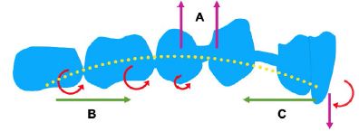
Figure 9: The bowing bending of CA causes the roller coaster effect. Clear aligner sagging (A), Counterclockwise moment (B), Clockwise moment (C).
Conclusions
This study determined that RCE occurs during premolar space closure with CAs, primarily due to the biomechanical properties of the aligners themselves. During space closure, a noticeable occlusal detachment of the CA was observed, accompanied by characteristic bow-bending deformation. Additionally, this study identified that CAs function as a pushing device, exerting a direct pushing force on the teeth. Thus, understanding the biomechanics of CAT is crucial for optimizing clinical outcomes. This includes enhancing torque control and anterior tooth intrusion, improving anchorage, increasing resistance to tipping and intrusion of posterior teeth, preventing bowbending deformation, and improving appliance retention.
Abbreviations
CBCT: Cone-Beam Computed Tomography; CA: Clear Aligner; CAT: Clear Aligner Treatment; FEM: Finite Element Model; 3D: Three-Dimensional; PDL: Periodontal Ligament; RCE: Roller Coaster Effect; EMR: En-Mass Retraction.
Availability of Data and Materials
The datasets used and or analysed during the current study are available from the corresponding author upon reasonable request.
Authors’ Contributions
Song Cang, Xiaosong Xiang, and Chunlin Wang conceptualized and designed the study, contributed to the manuscript framework, collected and analyzed the data, and drafted and revised the manuscript. Xiaosong Xiang and Chunlin Wang contributed equally as co-first authors. C. Maarten Suttorp and Frank A. D. T. G. Wagener revised the manuscript. Zhihao Wang assisted with data collection and analysis. All authors reviewed and approved the final manuscript..
Competing Interests
The authors declare that they have no competing interests.
Consent for Publication
Not applicable.
References
- Council of Orthodontics Professors (2020). Textbook of Orthodontics, 4th ed.; Daehan Narae Publishing House: Seoul, Korea.
- Profitt, W (2020). Contemporary Orthodontics, Elsevier: Amsterdam, The Netherlands.
- Bergomi M, Wiskott HW, Botsis J, Mellal A, Belser UC (2010). Load response of periodontal ligament: assessment of fluid flow, compressibility, and effect of pore pressure. J Biomech Eng.132: 014504. [crossref]
- Cao WQ, Chen FY, Gu YJ (2014). Three-dimensional finite element analysis of maxillary incisors with high traction pressure of J-hook. Stomatology.34: 257-260.
- Savignano R, Barone S, Paoli A, Razionale AV (2017). Advances on Mechanics, Design Engineering and Manufacturing.Springer International Publishing AG: Cham.405-414.
- Kim WH, Hong K, Lim D, Lee JH, Jung YJ, et al. (2020). Optimal Position of Attachment for Removable Thermoplastic Aligner on the Lower Canine Using Finite Element Analysis. Materials (Basel). 13: 3369. [crossref]
- Cortona A, Rossini G, Parrini S, Deregibus A, Castroflorio T (2020). Clear aligner orthodontic therapy of rotated mandibular round-shaped teeth: A finite element study. Angle Orthod. 90: 247-254.[crossref]
- Schupp W, Haubrich J, Neumann I (2010). Class II correction with the Invisalign system. J Clin Orthod. 44: 28-35.
- Barone S, Paoli A, Razionale AV, Savignano R (2017). Computational design and engineering of polymeric orthodontic aligners. Int J Numer Method Biomed Eng.33: e2839. [crossref]
- White DW, Julien KC, Jacob H, Campbell PM, Buschang PH (2017). Discomfort associated with Invisalign and traditional brackets: A randomized, prospective trial. Angle Orthod. 87: 801-808. [crossref]
- Gomez JP, Peña FM, Martínez V, Giraldo DC, Cardona CI (2015). Initial force systems during bodily tooth movement with plastic aligners and composite attachments: A three-dimensional finite element analysis. Angle Orthod.85: 454-60. [crossref]
- Mariko G, Wakana Y, Hitoshi K, Norio I, Koutaro M (2017). A method for evaluation of the effects of attachments in aligner-type orthodontic appliance: Three-dimensional finite element analysis, Orthodontic Waves.76: 207-214.
- Lu W, Li Y, Mei L, Li Y (2023). Preformed intrusion bulbs on clear aligners facilitate active vertical control in a hyperdivergent skeletal Class II case with extraction: A case report with 4-year follow-up. APOS Trends Orthod.13: 46-54.
- Roberts WE, Chang CH, Chen J, Brezniak N, Yadav S (2022). Integrating skeletal anchorage into fixed and aligner biomechanics. J World Fed Orthod.11: 95-106. [crossref]
- Rossini G, Schiaffino M, Parrini S, Sedran A, Deregibus A, et al. (2020). Upper second molar distalization with clear aligners: a finite element study. Applied Sciences.10: 7739.
- Schmidt F (2022). 3D Quantification of Orthodontic Tooth Movements for Treatment Planning and Monitoring[D]. Universität Ulm.
- Cattaneo PM, Dalstra M, Melsen B (2005). The finite element method: a tool to study orthodontic tooth movement. J Dent Res. 2005; 84: 428-33. [crossref]
- Vlaskalic V, Boyd R (2001). Orthodontic treatment of a mildly crowded malocclusion using the Invisalign System. Australian orthodontic journal. 17: 41-46.[crossref]
- Jiang T, Wu RY, Wang JK, Wang HH, Tang GH (2020). Clear aligners for maxillary anterior en masse retraction: a 3D finite element study. Sci Rep. 10: 10156. [crossref]
- Simon M, Keilig L, Schwarze J, Jung BA, Bourauel C (2014). Treatment outcome and efficacy of an aligner technique–regarding incisor torque, premolar derotation and molar distalization. BMC Oral Health.14: 68.[crossref]
- Venugopal A, Manzano P,Rengalakshmi S (2020). A Novel Temporary Anchorage Device Aided Sectional Mechanics for Simultaneous Orthodontic Retraction and Intrusion. Case reports in dentistry.
- Iliadi A, Koletsi D, Eliades T (2019). Forces and moments generated by aligner-type appliances for orthodontic tooth movement: A systematic review and meta-analysis. Orthod Craniofac Res. 22: 248-258. [crossref]
- Sheng Y, Guo HM, Bai YX, Li S (2020). Dehiscence and fenestration in anterior teeth: Comparison before and after orthodontic treatment. J Orofac Orthop.81: 1-9. [crossref]
- Zhu Y, Hu W, Li S (2021). Force changes associated with differential activation of en-masse retraction and/or intrusion with clear aligners. Korean J Orthod.51: 32-42. [crossref]
- Machado RM (2020). Space closure using aligners. Dental Press J Orthod. 25: 85-100.
- Jiang T, Jiang YN, Chu FT, Lu PJ, Tang GH (2021). A cone-beam computed tomographic study evaluating the efficacy of incisor movement with clear aligners: Assessment of incisor pure tipping, controlled tipping, translation, and torque. Am J Orthod Dentofacial Orthop. 159: 635-643. [crossref]
- Baldwin DK, King G, Ramsay DS, Huang G, Bollen AM (2008). Activation time and material stiffness of sequential removable orthodontic appliances. Part 3: premolar extraction patients. Am J Orthod Dentofacial Orthop.133: 837-45. [crossref]
- Buschang PH, Ross M, Shaw SG, Crosby D, Campbell PM (2015). Predicted and actual end-of-treatment occlusion produced with aligner therapy. Angle Orthod. 85: 723-7. [crossref]
- Liu L, Zhan Q, Zhou J, Kuang Q, Yan X, et al. (2021). Effectiveness of an anterior mini-screw in achieving incisor intrusion and palatal root torque for anterior retraction with clear aligners. Angle Orthod. 91: 794-803. [crossref]
- Lombardo L, Arreghini A, Ramina F, Huanca Ghislanzoni LT, Siciliani G (2017). Predictability of orthodontic movement with orthodontic aligners: a retrospective study. Prog Orthod.18: 35.[crossref]
- Mehta S, Patel D, Yadav S (2021). Staging Orthodontic Aligners for Complex Orthodontic Tooth Movement. Turk J Orthod. 34: 202-206. [crossref]
- Liu W, Shao J, Li S, Al-Balaa M, Xia L et al. (2021). Volumetric cone-beam computed tomography evaluation and risk factor analysis of external apical root resorption with clear aligner therapy. Angle Orthod.91: 597-603. [crossref]
- Li Y, Deng S, Mei L, Li Z, Zhang X, et al. (2020). Prevalence and severity of apical root resorption during orthodontic treatment with clear aligners and fixed appliances: a cone beam computed tomography study. Prog Orthod. 21: 1. [crossref]
- Hahn W, Zapf A, Dathe H, Fialka-Fricke J, Fricke-Zech S, et al. (2010). Torquing an upper central incisor with aligners–acting forces and biomechanical principles. Eur J Orthod. 32: 607-13. [crossref]
- Dai FF, Xu TM, Shu G (2019). Comparison of achieved and predicted tooth movement of maxillary first molars and central incisors: First premolar extraction treatment with Invisalign. Angle Orthod. 89: 679-687. [crossref]
- Dai FF, Xu TM, Shu G (2021).Comparison of achieved and predicted crown movement in adults after 4 first premolar extraction treatment with Invisalign. Am J Orthod Dentofacial Orthop. 160: 805-813. [crossref]
- Swain BF, Ackerman JL (1969). An evaluation of the Begg technique. Am J Orthod. 55: 668-87.[crossref]
- Papadimitriou A, Mousoulea S, Gkantidis N, Kloukos D (2018). Clinical effectiveness of Invisalign® orthodontic treatment: a systematic review. Prog Orthod. 19: 37.[crossref]
- Lie Ken, Jie RKP (2018). Treating Bimaxillary Protrusion and Crowding with the Invisalign G6 First Premolar Extraction Solution and Invisalign Aligners. APOS Trends in Orthodontics. 8: 219-224.
- Geron S, Shpack N, Kandos S, Davidovitch M, Vardimon AD (2003). Anchorage loss–a multifactorial response. Angle Orthod.73: 730-7.
- Klontz HA (1996). Tweed-Merrifield sequential directional force treatment. Seminars in orthodontics. 2: 254-267. [crossref]
- Lin LY, Chang CH, Roberts WE (2020). Bimaxillary protrusion and gummy smile treated with clear aligners: Closing premolar extraction spaces with bone screw anchorage. APOS Trends in Orthodontics. 10: 120-131.
- Ojima K, Dan C, Nishiyama R, Ohtsuka S, Schupp W (2014). Accelerated extraction treatment with Invisalign. J Clin Orthod. 48: 487-99. [crossref]
- Upadhyay M, Arqub SA (2022). Biomechanics of clear aligners: hidden truths & first principles. J World Fed Orthod.11: 12-21. [crossref]
- Al-Balaa M, Li H, Ma Mohamed A, Xia L, Liu W, et al. (2021). Predicted and actual outcome of anterior intrusion with Invisalign assessed with cone-beam computed tomography. Am J Orthod Dentofacial Orthop.159: e275-e280. [crossref]
- Khosravi R, Cohanim B, Hujoel P, Daher S, Neal M, et al. (2017). Management of overbite with the Invisalign appliance. Am J Orthod Dentofacial Orthop. 2017; 151: 691-699. [crossref]
- Bertossi D, Galzignato PF, Conti G, Luciano U, Gualdi A, et al. (2018). Histological evaluation of periodontal ligament in human after orthodontic treatment with piezosurgery and monolateral tooth dislocation and ligament distraction technique: a first morphologic and histologic evaluation. J Biol Regul Homeost Agents. 32: 9-13. [crossref]
- Skaik A, Wei XL, Abusamak I, Iddi I (2019). Effects of time and clear aligner removal frequency on the force delivered by different polyethylene terephthalate glycol-modified materials determined with thin-film pressure sensors. Am J Orthod Dentofacial Orthop. 155: 98-107. [crossref]
- Tartaglia GM, Mapelli A, Maspero C, Santaniello T, Serafin M, et al. (2021). Direct 3D Printing of Clear Orthodontic Aligners: Current State and Future Possibilities. Materials (Basel). 14: 1799. [crossref]