Abstract
In-111-Octreotide infusion, via intrahepatic catheterization is well established technique in our Institution in hepatocellular carcinoma and neuroendocrine tumors treatment. In order to facilitate repetitive infusions of our patients, a method of implanted ports use, gave a simpler therapeutic way but also improved therapy results. Our aim is to show that radiopharmaceutical fluid flow through implanted port is rich; the absorbed dose in the tumor increased for best therapy results.
Surgically implanted ports have been used in repetitive intra-arterial In-111 radiolabeled Octreotide infusions for 22 patients with hepatocellular carcinoma and similarly 18 patients with neuroendocrine tumors in a continuous base. A percutaneous implantation procedure facilitates safe and less invasive radiopharmaceutical infusions for the treatment. We have focused on the interventional techniques for percutaneous implantation of a vascular access device, consisting of an implantable port, to perform In-111 Octreotide infusions. Hepatic arterial infusion radiotherapy employs a hepatic artery catheter as a conduit to achieve a high concentration of radiolabeled agent to liver tumors. It is performed using less-invasive percutaneous image guided procedures. Various techniques were used to ensure high concentration of radiopharmaceutical in liver tumors, as there are many anatomical hepatic arterial variations and complicated blood flow patterns. These techniques are composed of arterial redistribution by embolization, percutaneous catheter placement, evaluation and management of flow patterns that reflect In-111 Octreotide distribution.
Using fluid flow theory, we describe blood flow alterations that could be performed to obtain selective radiopharmaceutical distribution to the target area and avoid side effects caused by the accumulation of the radiolabeled agent into non tumor areas. By steady, laminar and disturbed flow equations, the rich distribution of our agent in the scintigraphy imaging of the tumor, by the implanted ports technique, can be explained.
The factors affecting hepatic arterial flow in tumor feeding artery were analyzed. The patency rate of the hepatic artery was significantly higher in patients with catheter placement using fixed port method than those undergo fully interventional catheterization. A ratio of 5: 1 to 3: 1 flow increase was calculated through poiseuille flow and Reynolds number for circular pipe.
We consider that in continuous therapy, it is important to use the simplest fixed port method for percutaneous catheter placement instead of interventional catheterization, in order to increase absorbed dose into tumor for best response of radionuclide therapy.
Keywords
Blood flow, Laminar flow, Poiseuille law, Implanted Port, Arterial infusion, In-111-Octreotide Therapy
Blood Flow in Arteries
Blood flow in arteries principally is an unsteady phenomenon. Normal arterial flow is laminar but secondary flows are generated at curves and branches. Arteries may change with the varying hemodynamic conditions. Unusual hemodynamic conditions could create an abnormal biological response. Velocity profile skewing creates pockets, in which the direction of the wall shear stress oscillates.
The study of arterial blood flow will lead to the prediction of individual hemodynamic flows in any patient, the development of diagnostic tools to quantify disease and the design of devices that mimic or alter blood flow.
The blood flow in human arterial system can be considered as a fluid dynamics problem. Simulation of blood flow in the arterial network system will provide a better understanding of the physiology of human body. Simulation studies of blood flow in the diseased condition can diagnose the health problem easily. There are two distinctly different types of blood fluid flow. The first type is known as laminar, the second as turbulent flow.
In laminar flow the fluid particles move along smooth paths in layers with every layer (lamina) sliding smoothly over its neighbor. Laminar flow becomes unstable at high velocities and breaks down into turbulent flow. In turbulent flow the particles follow very irregular and erratic paths, their velocity vectors varying continually both in magnitude and direction [1, 2].
Steady Flow
Steady flow is that one where all conditions, such as velocity and pressure, at any point in a stream remain constant with respect to time. The definition is usually expanded to include flow in which the conditions fluctuate equally on both sides of a constant average value. Arterial flow is pulsatile and each flow may be analyzed in terms of a steady flow together with a number with superimposed sinusoidal components.
Steady flow of Newtonian fluids in rigid vessels is well understood and can serve as a starting point in the study of blood flow in arteries. Blood flow is also relevant as pulsatile flow and can be considered to be the sum of a steady component and a number of oscillatory components which interact neither with each other nor with the steady component [2].
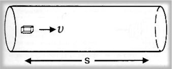
Figure 1. An element of fluid in steady flow at velocity υ takes a time t to traverse a distance s.
Laminar Flow in a Vessel
Flow is laminar when the velocity gradient is smooth and continuous.
Cross section of the vessel shows the laminae moving at different speeds; closest to the edge of the vessel, fluid moves slowly, though near the center moves quickly (2).
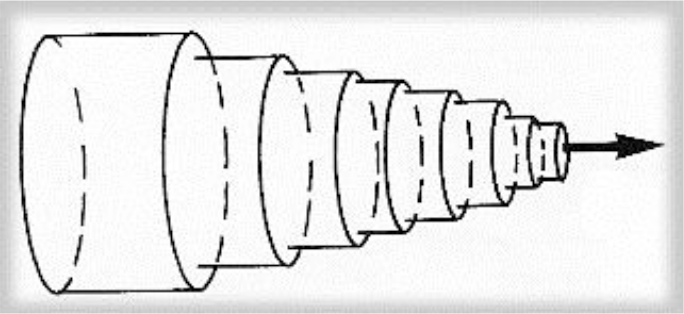
Figure 2. Schema of the laminar flow in a cylindrical vessel. The laminae slide over each other, binded by friction from within the fluid.
Poiseuille Flow
Steady laminar flow established in long cylindrical pipes is sometimes referred to as Poiseuille flow. This is a basic type of flow and blood moves in a series of concentric shells such that the velocity profile across the vessel is parabolic. Blood in the center of the vessel is moving most rapidly, though blood in contact with the vessel wall does not move. The velocity of any lamina at radius r from the center of the vessel may be expressed by
υ(r) = υmax (1-r2/R2) [1]
Where υmax is the velocity of the center stream and R the radius of the vessel.
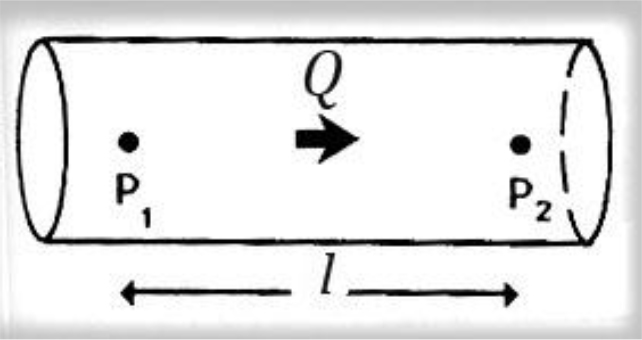
Figure 3. Poiseuille law, viscosity of fluid.
Steady flow discharge Q is sustained in a long rigid tube. The pressure over a length l is P2-P1. Poiseuille described how the steady flow of a fluid is influenced by its viscosity, showing that for a pressure difference P2–P1 along a length l of the vessel, the pressure and the flow discharge Q are related to, in the following way
P2–P1 = (8 l v/πr4) × Q [2]
Where v is the viscosity and r the radius of the vessel lumen.
Consequently, the fluid resistance increases with the fourth power of decreasing radius of the vessel lumen. So, halving the radius means that a 16-fold increase in pressure is required to maintain the same flow.
According to Poiseuille law the variation of velocity across the lumen of a long cylindrical pipe in steady viscous flow, is smooth and has the form of a paraboloid of rotation. (1–4)
Turbulent Flow
Laminar flow becomes unstable at high velocities and breaks down to turbulent flow. The point at which the transition between the two flow regimes occurs cannot be predicted exactly, but it is largely determined by the Reynolds number, Re, which for a circular pipe is defined as:
Re = υ.D/ν [3]
Where, υ is the average velocity of flow across the pipe, D the diameter of the pipe and v the kinematic viscosity.
Reynolds number (Re) is a dimensionless number that characterizes different flow regimes.
Laminar flow occurs at low Re, as a smooth, constant fluid motion, though turbulent flow because of flow instabilities occurs at high Re.
Turbulent flow may never be described as steady as there are continual fluctuations in both velocity and pressure at every point. 2.25 to 4.45 folds flow increase was calculated through poiseuille flow and Reynolds number, for cylindrical pipe. (4).
Blood Flow Energy
Fluid with sufficient kinetic energy is capable of flowing up a pressure gradient. The property of a fluid that determines the direction and speed of flow is its total fluid energy. Fluid energy can take several forms as the following. In real conditions these energy forms may be combined.
a. Pressure energy (P)
Pressure in a fluid may be thought of as the ability to do work, e.g. overcome viscous resistance; so pressure is a form of potential energy.
b. Kinetic energy (K)
Each volume of moving fluid has energy by virtue of its mass and motion, determined as ½ ρ.υ2, where ρ is the density and υ the velocity of flow.
c. Gravitational potential energy (G)
Fluid at a higher level than an arbitrary point is also capable of doing work; its weight imparts a potential energy equal to ρ.g.h, where, ρ the density, g the acceleration of gravity and h is the height. This gravitational energy may be transformed into kinetic energy by, e.g., allowing the fluid to flow down.
d. Viscous energy (V)
Flow against a viscous resistance described above may also be seen as a form of energy loss, in which kinetic or potential energy of the fluid is transferred to heat. With laminar flow the magnitude of this loss depends on vessel geometry.
In a single streamline of flow, the principle of conservation of energy holds that the sum of these individual energies, the total fluid Energy E, must remain constant at each point along the path of flow.
It is a difference in blood fluid energy that determines the direction and character of flow.
Mathematically, blood flow is described by Darcy’s law
F = ΔP/R [4]
Where F = blood flow, ΔP = pressure gradient, R = resistance
It is also described approximately by the following Hagen-Poiseuille equation
R = (v.L/r4(8/π) [5]
Where ν = blood fluid viscosity, L = length of tube, r = radius of tube
The viscosity of normal blood is about three times as great as the viscosity of water.
It is important to note that resistance to flow changes dramatically, with respect to the radius of the tube as already is referred for fluid flow in Poiseuille law [2–4].
In large arteries blood can be approximated as an homogeneous Newtonian fluid because the vessel size is much greater than the size of particles; particle interactions have a negligible effect on the flow. In smaller vessels, blood behavior is expressed as non-Newtonian [5].
Materials and Method
The treatment of hepatocellular carcinoma via the hepatic artery is based on the existence of arterial hyper vascularization of the tumor. For tumors bigger than 2 cm in diameter, more than 80% of their blood supply is drawn from the hepatic artery. Normal liver parenchyma draws more than 80% of blood from the portal vein. By delivery of radioactive agents into the hepatic artery, which represents almost exclusively the arterial supply to liver tumors, highly selective tumor uptake can be achieved [6].
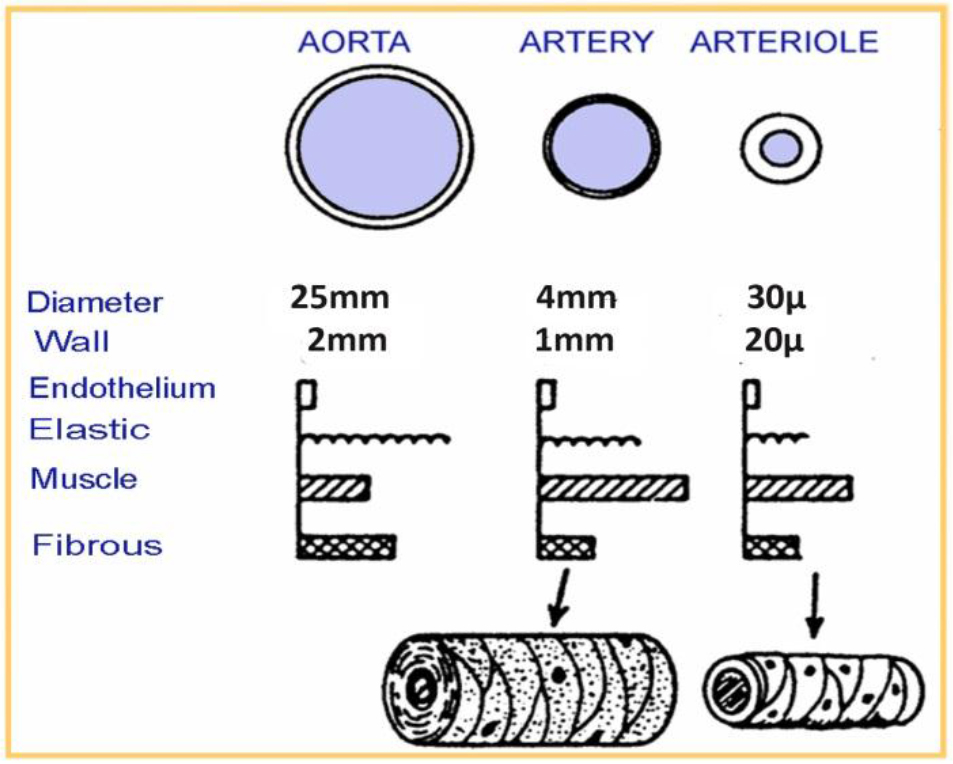
Figure 4. Human vessels sizes (aorta, artery, arteriole)
The theoretical rationale for hepatic artery infusion is based on the observation that hepatocellular carcinoma and neuroendocrine tumors are hyper vascular tumors and derive the majority of their blood supply from the hepatic artery.
In general the radiopharmaceutical is delivered at the lobar artery level to be distributed to numerous tumors in that lobe.

Figure 5. (Left) an histologic sample of normal (A) and tumor liver cells (B).Cell dimensions and distances between cell surface and nuclei show that DNA lies within the micrometer range of In-111 emissions. (Right) Hepatic artery supplied the tumor is the liver entrance for infusion.
Individually determined patient-specific activities are used. In the case of main hepatic artery injection, radiation is distributed to both lobes of the liver. If the lesions are limited to one lobe, the catheter can be selectively inserted either into the left or right lobar artery supplying the affected lobe, thus sparing the contralateral.
In selected cases, hyper selective, single segment treatments can be considered.
Gentle infusion, by a steady low pressure, should be used to strictly avoid backflow (fig 6).
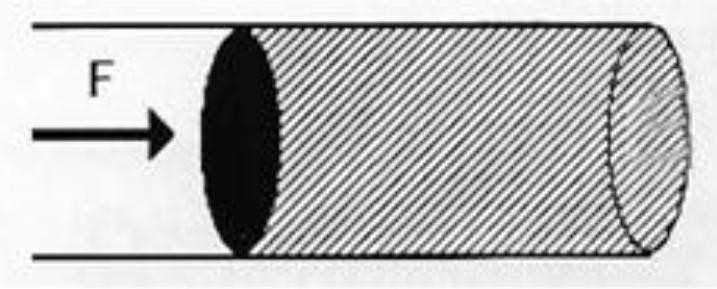
Figure 6. In order the flow be maintained against viscosity, a force F is applied to the fluid.
Gentle infusion (no excessive pressure) should be used to strictly avoid backflow.
Indium -111- Octreotide
Indium-111 (111In) is a radioisotope that was introduced for hepatocellular carcinoma and neuroendocrine tumor cancer cells diagnosis. It is also successfully used for neuroendocrine tumor radio-immunotherapy.
a) Production and Physical Characteristics of In-111
In-111 is produced by cyclotron from Cd-112 collision with protons of energy 2.8 MeV according to the nuclear reaction Cd-112 (p, 2n) In-111. Radioactive In-111 decays by physical half-life time of 2.83 days. The type, energy and emission ratio for In-111 decay, are displayed in Table 1.
Table 1. Indium-111(In111) Decay Chart
|
In-111 Decay Chart |
||
|
Type of decay |
Energy (keV) |
Emission ratio (Bq·s) – 1 |
|
Photons |
150.8 |
3·10–5 |
|
Photons |
171.3 |
0.906 |
|
Photons |
245.4 |
0.941 |
|
Electrons IT* |
145 – 170 |
0.1 |
|
Electrons IT* |
218 – 245 |
0.06 |
|
Auger electrons |
19 – 25 |
0.16 |
|
Auger electrons |
2.6 – 3.6 |
1.02 |
|
Auger electrons |
0.5 |
1.91 |
IT, Internal Transform
Purity of the final product of In-111 is affected by the undesired isotopes In-110m, In-110 and In-114m that are not possible to spare from In-111 due to the similar chemical characteristics of these isotopes with In-111.
Isotopes In-110m and In-110, do not affect dosimetry of radioisotopes labeled with In-111, as these undesired isotopes have minor presence and short half-life time (4.9h and 1.1h, respectively). On the contrary, In-114m that is produced from Cd-114 according to a (p, n) nuclear reaction, has 49.51 days half-life time and decays by internal transition (96.9%) and electron capture (3.2%) with emission of photons at (192, 558 and 725) keV. In-114m affects dosimetry due to its long half-life time [7].
The Flow Discharge Q depends on the volume V of the fluid that passes in time interval t
That is Q = V/t [6a]
Flow Discharge is also determined by the multiplication of the cross section of the object with mean velocity
Q = S × υ[6b]
Then mean velocity depends on flow discharge and is inversely proportional to the cross section of the tube
υ = Q / S [6c]
Angiographic catheter cross section SA is smaller than Port catheter cross section SP, (SP > SA) consequently the Port flow QP is greater than Angiographic flow QA.
QP/QA = SP/SA > 1 [6d]
Assuming that the velocity in angiographic tube is obtained equal to the velocity in port tube vA = vP, we consider (by equation 6d) that Port Flow QP > Angiographic Flow QA.
b) In-111 uptake and biokinetic properties
The radiopharmaceutical In-111-DTPA-D-Phe-1 octreotide is a peptide composed of 8 amino acids and is an analogue of the active part of the peptide hormone somatostatin In-111-octreotide. It is used for radio immunotherapy for neuroendocrine tumors of the gastro hepatic system. Octreotide is a somatostatin analogue used for labeling In-111. Somatostatin is a peptide of the gastro enteric system that inhibits the production of the grow hormone.
There is an over expression of the somatostatin receptors at the surface of the neuroendocrine tumor cancer cells. In-111-octreotide is bounded to the somatostatin inhibitors and transferred into the cancer cell. Auger electrons that are emitted from In-111 can damage the DNA of the cancer cell.
In palliative treatment use, the radiopharmaceutical entrance into the tumor cell and its destructive effect to DNA by emission of Auger and internal conversion electrons has been exploited earlier [8, 9].
The Peptide Receptor Radionuclide Therapy (PRRT), a somatostatin-analogue-based targeted therapy, is a field in the palliative treatment of Neuro Endocrine Tumors (NET) with very encouraging data. The treatment modality utilizes radioactive substances that are conjugated with various somatostatin analogues such as octreotide.
Intravenously administrated, these drugs bind to the somatostatin receptor localized on the tumor cells. The ligand–receptor complex is internalized and the attached radiation has the potential to destroy the tumor cells.
The side effects are few and mostly mild, in particularly when treatment protocols consider renal protective agents. Initially used In-111-DTPA-[D-Phe1]-octreotide achieved positive results, whereas stable disease was seen in 42% to 81% of patients and partial remission rates up to 8%. However, because of the limited tissue penetration range of In-111, In-111 coupled peptides are rather ineffective for PRRT and their utilization should be restricted for hepatocellular carcinoma therapeutic purposes.
Auger electrons with particle ranges (.02–10) μm and Internal Conversion electrons with ranges (200–550) μm that In-111 emits during its transformation procedure are extremely short. In large arteries blood can be approximated as homogeneous Newtonian fluid because the vessel size is much greater than the size of particles; particles’ interactions have a negligible effect on the flow [5, 6, 8, 13].
Implanted Port /Arterial Infusion
Surgically implanted ports have been used in repetitive intra-arterial In-111 radiolabeled Octreotide infusions for 22 patients with hepatocellular carcinoma and similarly 18 patients with neuroendocrine tumors in a continuous base. A percutaneous implantation procedure facilitates safe and less invasive radiopharmaceutical infusions for the treatment. We have focused on the interventional techniques for percutaneous implantation of a vascular access device consisting of an implantable port, to perform In-111-Octreotide infusions.
Hepatic arterial infusion radionuclide therapy employs a hepatic artery catheter as a duct to achieve a high concentration of radiolabeled agent to liver tumors. Various techniques were used to ensure high concentration of radiopharmaceutical in liver tumors as there are many anatomical hepatic arterial variations and complicated blood flow patterns. They are composed of arterial redistribution by embolization, percutaneous catheter placement and evaluation and management of flow patterns reflecting In-111 octreotide distribution.
Using fluid flow theory we describe details of the alteration of blood flow by first pass embolization that can be performed to obtain selective radiopharmaceutical distribution to the target area and to avoid side effects caused by the accumulation of the radiolabeled agent into non tumor areas.
Different hypothetical flow mechanisms lead to different patterns of strain relaxation with time. Representative tissue properties show blood fluid drainage into the local microvasculature to be the dominant flow-related stress/strain relaxation mechanism; due to drainage into the microvasculature is on the order of 5–10 sec. This is the relaxation time of strain in solid tumors under realistic applied pressure magnitudes. The magnitude of the strain relaxation can be as high as approximately 0.4% strain, well within the range of strains measurable by elastography.
A rich distribution of the In-111 radiopharmaceutical that is recorded in the scintigraphy imaging of the tumor, by the implanted ports technique, is explained by steady, laminar and disturbed flow equations [10, 11].
a) Tip-Fixation method
In order to facilitate repetitive infusions of our patients, a method of implanted ports, gave a simpler therapeutic way but also improved therapy results.
Our aim is to show that radiopharmaceutical fluid flow through implanted port is rich and the absorbed dose in the tumor increased for best therapy results.
Implanted ports have been used in repetitive intra-arterial In-111 Octreotide infusions.
The catheter should be placed directly into the artery supplying the tumor. Since the position of the catheter tip cannot be changed after placement, hemodynamic alterations must be taken into consideration.
Patients, with histologically confirmed hepatocellular carcinoma or neuroendocrine tumors lesions located in liver and with normal kidney function, were infused with mean activity of 4500 MBq In-111 – octreotide.
The technique is composed of arterial redistribution, percutaneous catheter placement applying “tip-fixation method, ” evaluation & management of flow patterns that reflect radiopharmaceutical distribution.
The infusion was performed through a port attached to the hepatic artery. The hepatic artery port makes the therapy more comfortable for the patient as in this way the hepatic artery angiography catheterization, at each therapeutic session, is avoided.
Port chamber is made of titanium & silicone membrane (diameter12mm). It is 28 mm long and 13.5 mm wide. Inner diameter of port catheter is 1.2 mm and outer diameter is 2.5mm [12].
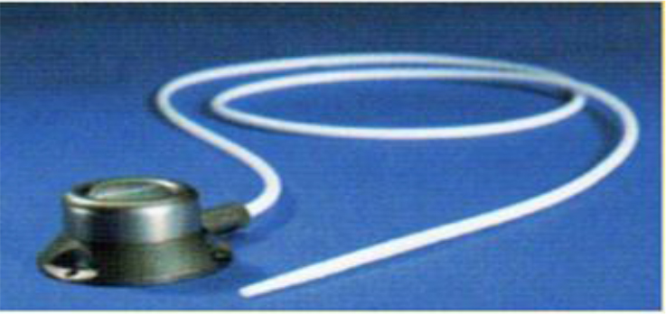
Figure 7. Percutaneously implantable catheter-port system.
The “tip-fixation method uses the gastroduodenal artery. Hepatic arterial infusion radiotherapy employs a hepatic artery catheter as a duct to achieve a high concentration of radiolabeled agent to liver tumors.
For the “tip-fixation method, a distal branch of the hepatic artery could also be used to fix the catheter tip. Sometimes, in cases of lower tumor load, a more selective delivery at the segmental artery level is possible.
This is proved to be the best method to give better uptake of the radiopharmaceutical by the tumor. The infusion of the radiopharmaceutical was performed directly to patient liver through the port that was attached to the hepatic artery.
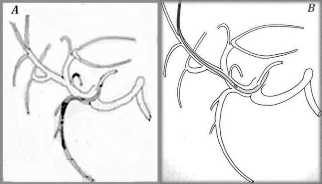
Figure 8. The “tip-fixation method” using the gastroduodenal artery (A) or a distant hepatic artery (B)
To fix the tip of the indwelling catheter, the gastroduodenal artery (GDA) is most commonly used. When using the GDA, an indwelling side-holed catheter is inserted into the GDA. However, if necessary, it is possible to use other arteries.
Scintigraphy
Patient specific dose estimation for the tumor and healthy tissue is very important for radiopharmaceutical therapeutic applications as this is the most accurate way to assign an administered dose to the best therapeutic result. It is also assistance to the physician in order to avoid side effects of the therapy and compare the treatment results to other related therapies as external radiotherapy [13].
Scintigraphy is performed immediately after radiopharmaceutical infusion and at 24h and at 48h post-infusion. Individually determined patient-specific activities are used. Quantitative whole-body scintigraphy imaging one week post therapy is recommended to confirm the distribution of the radiopharmaceutical. This is proved to be the best method to give better uptake of the radiopharmaceutical by the tumor.
Gamma camera is calibrated in order to estimate source organ activity considering count rate, patient’s body diameter and source organ size [14].
Average activity (6.3+-2.3) GBq per session was administered at monthly intervals. Infusion repetition did not exceed the 12th fold.
Results
The patient individualized dosimetry calculations were based on anterior and posterior scintigraphy images that were acquired immediately after radiopharmaceutical infusion, through hepatic arterial port and at 24 and 48 h post-infusion.
The results showed that the tumor absorbed dose ranged from 2.5mGy/MBq to 18.4mGy/MBq depending on the lesion size [13]. The average absorbed dose per session to a tumor for a spherical mass of 10 gr was estimated to be 10.8 mGy/MBq, depending on the histotype of the tumor.
The organ average radiation dose estimation after In-111-DTPA-Phe1-octreotide trans-hepatic infusion was found as follows:
|
(a) Liver Tumor |
10.80 |
mGy/MBq |
|
(b) Liver organ |
0.14 |
mGy/MBq |
|
(c) Kidneys |
0.41 |
mGy/MBq |
|
(d) Spleen |
1.40 |
mGy/MBq |
|
(e) Pancreas |
0.13 |
mGy/MBq |
|
(f) Bone marrow |
0.003 |
mGy/MBq |
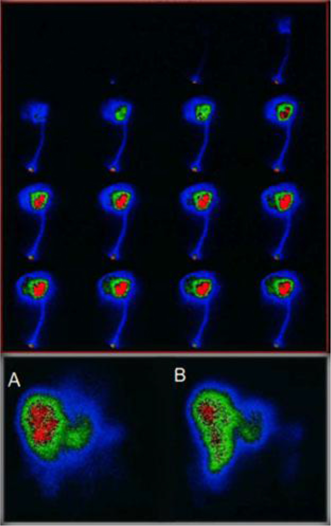
Figure 9. Above First pass infusion for selective In-111 Octreotide distribution to the target area. below (A) 1h post infusion via arterial port, (B) 1h post angiography thin catheter infusion.
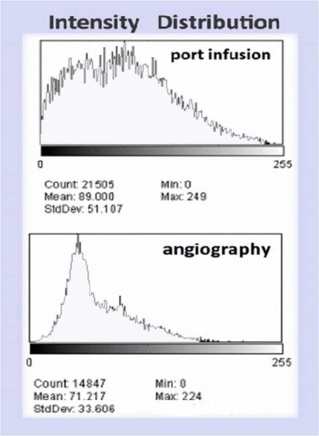
Figure 10. (Above) Intensity histogram of In111 Octreotide distribution by port infusion (catheter diameter 1.2mm) and (Below) Intensity histogram of In111-Octreotide distribution by angiography (catheter diameter 0.8mm)
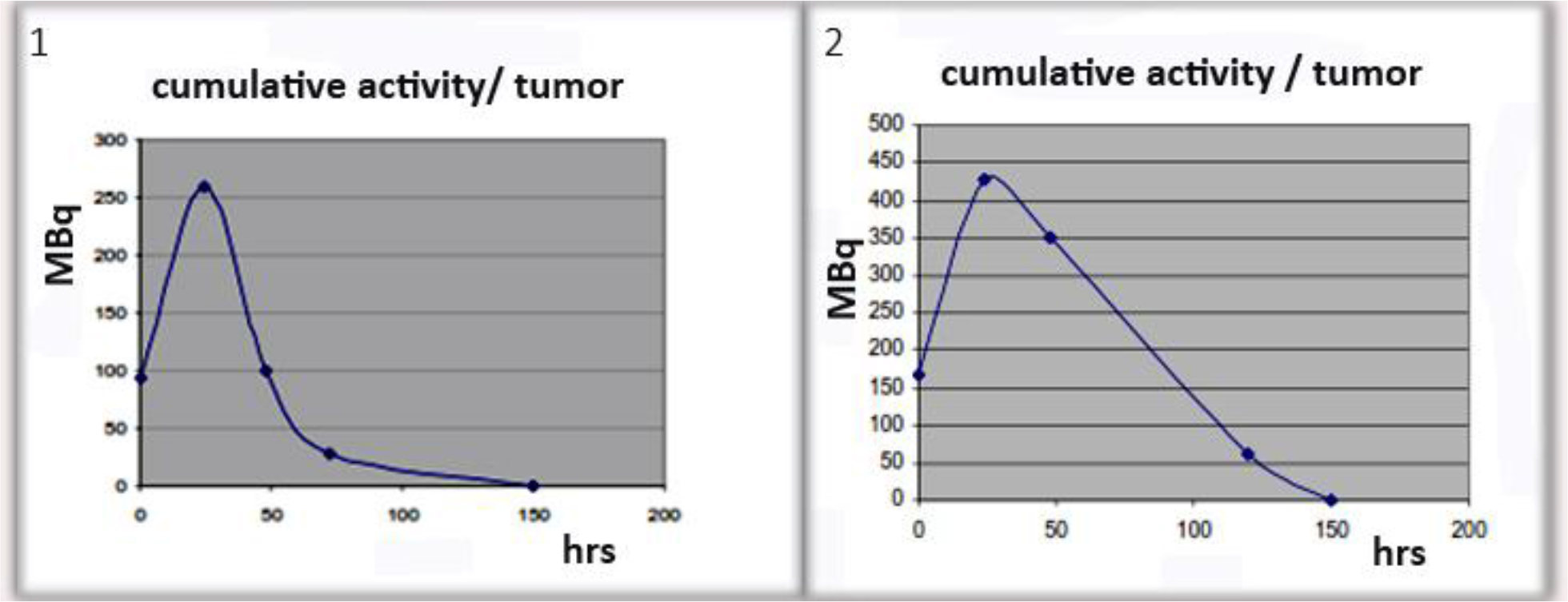
Figure 11. Examples of cumulative activity to tumor
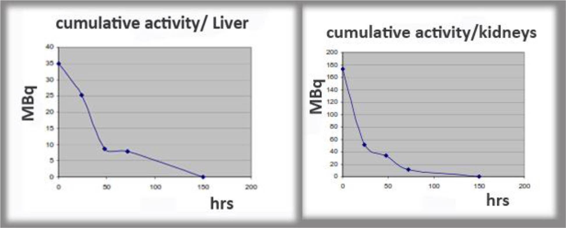
Figure 12. Examples of cumulative activity to critical organs.
Discussion
The factors affecting hepatic arterial flow in tumor feeding artery were analyzed. The patency rate of the hepatic artery was significantly higher in patients with catheter placement using fixed port method than those undergo fully interventional catheterization. A ratio of 5: 1 to 3: 1 flow increase was calculated through poiseuille flow and Reynolds number for circular pipe.
The infusion of the radiopharmaceutical was performed directly to patient liver through a port that was attached to the hepatic artery. Percutaneously implantable catheter-port system placement is safe and technically feasible for use in the hepatic artery.
This is proved to be the best method to give better uptake of the radiopharmaceutical by the tumor. Patient specific dose estimation for the tumor and healthy tissue is very important for radiopharmaceutical therapeutic applications as this is the most accurate way to assign an administered dose to the best therapeutic result [13–15]. It is also assistance to the physician in order to avoid side effects of the therapy and compare the treatment results to other related therapies as external radiotherapy.
In the case of main hepatic artery injection, radiation is distributed to both lobes of the liver. If the lesions are limited to one lobe, the catheter can be selectively inserted either into the left or right lobar artery supplying the affected lobe, thus sparing the contralateral. In selected cases, hyper selective (i.e. single segment) treatments can be considered.
Patient specific dosimetry calculations help the physician to optimize the planning of the treatment, avoid side effects to healthy tissue and assign administered dose to treatment results.
Conclusion
We consider that in continuous therapy, it is important to use the simplest fixed port method for percutaneous catheter placement instead of interventional catheterization, in order to increase absorbed dose into tumor for best response to radionuclide therapy. A percutaneous implantation procedure facilitates safe and less invasive radiopharmaceutical infusions for multiple treatments. Implanted ports have been used in repetitive intra-arterial In-111 Octreotide infusions. The patency rate of the hepatic artery was significantly higher in patients with catheter placement using fixed port method than those undergo fully interventional catheterization. Percutaneously implantable catheter-port system placement is safe and technically feasible for use in the hepatic artery.
Advantages of the use of intra-arterial radionuclide agents are the ability to deliver high doses of radiation to small target volumes, the relatively low toxicity profile, the possibility to treat the whole liver including microscopic disease and the feasibility of combination with other therapy modalities. Disadvantages are mainly due to radioprotection problems.
Percutaneous image-guided catheter placement for hepatic arterial infusion radionuclide therapy is technically safe and provides a viable alternative to traditional methods of hepatic artery access. However, a thorough knowledge of hepatic arterial anatomy, potential of complicated blood flow patterns and management of the infusion devices will ensure a high likelihood of tumor-only delivery of the radionuclide agent.
In summary, we modified the technique of radiologic placement of a catheter and port system for hepatic arterial infusion internal radiotherapy by fixing the catheter tip to the vessel and infusing radionuclide agents from the side hole of the catheter. We conclude that this technique is a safe and not unduly time-consuming method that obviates surgical laparotomy and represents a significant therapeutic advance in the medical oncology field for patients with liver malignancies.
Our intention is to study further, the behavior of the radionuclide fluid as is inserting in arteries and arterioles.
References
- Evans, DH, McDicken, WN, Skidmore, R., and Woodcock, JP, 1989, Doppler ultrasound: Physics, instrumentation, and clinical applications, John Wiley & Sons
- Taylor, Kenneth JW, Burns Peter N, Wells Peter NT (1987) Clinical Applications of Doppler Ultrasound, Raven Press 1988
- Ku David N (1997) Blood flow in arteries, Annual Review of Fluid Mechanics 29: 399–434
- Sankar DS, Hemalatha K (2007) A non-Newtonian fluid flow model for blood flow through a catheterized artery—Steady flow, Applied Mathematical Modelling 31: 1847–1864.
- Blessy Th, Sumam KS (2016) Blood Flow in Human Arterial System-A Review, Procedia Technology 24: 339–346.
- Giammarile F, Bodei L, Chiesa C, Flux G, et al (2011) Therapy, Oncology and Dosimetry Committees, EANM procedure guideline for the treatment of liver cancer and liver metastases with intra-arterial radioactive compounds, EJNMMI 38: 1393–406.
- Lyra ME Andreou M. Georgantzoglou A et al, (2013) Radionuclides Used in Nuclear Medicine Therapy – From Production to Dosimetry, Current Medical Imaging Reviews. Bentham Science Publishers 9: 51–75.
- Limouris GS, Chatziioannou A, Kontogeorgakos D. et al., 2008, Selective hepatic arterial infusion of In-111-DTPA-Phe1-octreotide in neuroendocrine liver metastases ejnmmi 35: 1827–1837.
- Virgolini I, Szilvasi I, Kurtaran et al. (1998) Indium-111-DOTA-Lanreotide: biodistribution safety and radiation absorbed dose in tumor patients. JNM 39: 1928–1936.
- Arai Y, Takeuchi Y, Inaba Y, Yamaura H, et al. (2007) Percutaneous catheter placement for hepatic arterial infusion chemotherapy, Techniques in vascular and interventional radiology 10: 30–37.
- Tanaka T, Arai Y, Inaba Y, Matsueda K, et al (2003) Radiologic placement of side-hole catheter with tip fixation for hepatic arterial infusion chemotherapy. Journal of vascular and interventional radiology 14: 63–68.
- Lyra ME, Limouris GS (2009) In-111 radiolabelled Octreotide therapy -Arterial infusion strategy using implanted ports versus Artery Catheterization- EJNMMI 36: 260–80.
- Vamvakas I, Lagopati N, Andreou M, et al, (2009) Patient specific computer automated dosimetry calculations during therapy with 111In Octreotide. European J of Radiography 1: 180–183.
- EANM Guideline (2010) Ellinor Busemann Sokole, Anna Płachcínska, Alan Britten with contribution from the EANM Working Group Maria Lyra Georgosopoulou, Wendy Tindale, Rigobert Klett, Routine quality control recommendations for nuclear medicine instrumentation, EJNMMI 37: 662–671.
- Maecke H R, Reubi Jean-Claude (2011) Somatostatin Receptors as Targets for Nuclear Medicine Imaging and Radionuclide Treatment JNM 39: 1928–1936.